
Air inflation device for high-pressure chamber and low-pressure chamber of buffering strut of aircraft landing gear

A technology for aircraft landing gear and buffer struts, which is applied to mechanical equipment, springs, shock absorbers, etc., can solve the problem of poor air tightness between the high and low pressure cavities between the inflatable equipment and the landing gear buffer strut, inaccurate control of the inflation volume, and the inflating process. Complex problems, to achieve the effect of good airtight performance, simple structure, precise control of air volume

Active Publication Date: 2015-04-01
HARBIN TONGHANG TECH DEV
View PDF8 Cites 2 Cited by
  • Summary
  • Abstract
  • Description
  • Claims
  • Application Information

AI Technical Summary

Problems solved by technology

[0004] The purpose of the present invention is to provide a high and low pressure cavity inflation device for the landing gear buffer strut to solve the problem of the airtightness between the inflatable device and the landing gear buffer strut high and low pressure cavity due to the complex structure of the existing inflation device and the complicated inflation process. Poor, the problem of inaccurate inflation control

Method used


Image

  • Air inflation device for high-pressure chamber and low-pressure chamber of buffering strut of aircraft landing gear
  • Air inflation device for high-pressure chamber and low-pressure chamber of buffering strut of aircraft landing gear

Examples


Embodiment Construction

[0012] Preferred embodiments of the present invention will be described in detail below with reference to the accompanying drawings.

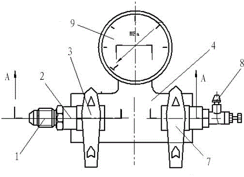
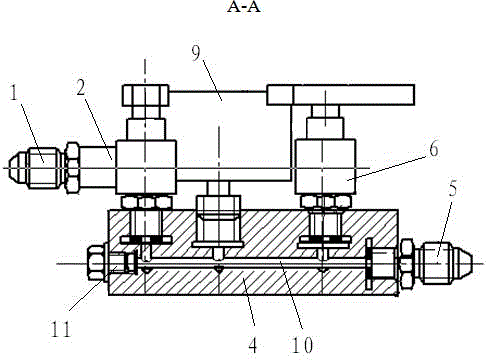
[0013] As shown in the figure, the high and low pressure chamber inflation equipment for the cushioning strut of the landing gear of the aircraft according to the present invention includes a first straight-through 1, an inflation ball valve 2, an inflation switch 3, a main valve body 4, a second straight-through 5, a deflation ball valve 6, and a discharge valve. Air switch 7, fine-tuning switch 8 and pressure gauge 9; said main valve body 4 is provided with a valve cavity 10 horizontally inside, the left end of the valve cavity is blocked by a plug 11, the right end of the valve cavity 10 is connected with the second straight-through 5, the second Straight through 1 is connected with inflatable ball valve 2, and described inflatable ball valve 2 and deflated ball valve 6 are arranged side by side, and inflated ball valve 2 and deflated ball va...


PUM


Abstract

The invention discloses an air inflation device for a high-pressure chamber and a low-pressure chamber of a buffering strut of an aircraft landing gear and relates to an air inflation device, which aims to solve the problems of complex structure, complicated air inflation process, poor airtight performance between the air inflation device and the high-pressure chamber and the low-pressure chamber of the buffering strut of the aircraft landing gear and inaccurate control on the inflating volume of the existing air inflation device. A main valve body is internally and horizontally provided with a valve cavity, wherein the left end of the valve cavity is blocked by a choke plug; the right end of the valve cavity is connected with a second direct connection joint; the first direct connection joint is connected with an air inflation ball valve; the air inflation ball valve and an air discharging ball valve are communicated with the valve cavity; an air inflation switch is connected with the air inflation ball valve; an air discharging switch is connected with the air discharging ball valve; a fine tuning switch is mounted on the air discharging ball valve; a pressure gage is located between the air inflation ball valve and the air discharging ball valve; the pressure gage is mounted on a main valve body and is communicated with the valve cavity; the first direct connection joint is connected with a high-pressure nitrogen cylinder; the second direct connection joint is connected with the high-pressure chamber and the low-pressure chamber of the buffering strut of the aircraft landing gear. The air inflation device is simple in structure; the structure is simplified while the airtight performance is greatly improved.

Description

technical field [0001] The invention relates to an inflatable device, in particular to an inflatable device for high and low pressure chambers of buffer struts of an aircraft landing gear, and belongs to the technical field of aircraft inflatable devices. Background technique [0002] The main device for an aircraft to take off and land is the landing gear, which is a device used to support the weight of the aircraft and bear the corresponding load when the aircraft is parked, taxied, taken off, and landed on the ground. It dissipates and absorbs the impact energy of the aircraft during landing and taxiing. [0003] When the aircraft is landing and rolling, the aerodynamic lift it receives is less than the gravity of the aircraft, the landing gear will be supported by the ground and the friction between the ground and the wheels. The force on the wheel and the moment relative to the center of gravity of the aircraft are an important part of the resultant force and moment on...

Claims


Application Information

Patent Timeline
Patent Type & Authority Applications(China)
IPC IPC(8): F16F9/43
CPCF16F9/43
Inventor 赵书斌刘世峤
Owner HARBIN TONGHANG TECH DEV
Learn More