Eureka AIR delivers breakthrough ideas for toughest innovation challenges, trusted by R&D personnel around the world.

Compression mechanism for rotary compressor and rotary compressor with same

A technology of rotary compressor and compression mechanism, applied in the field of compressor manufacturing, can solve the problems of weakening of the axial rigidity of the auxiliary bearing, unbalanced magnetic pulling force, reduced energy efficiency, etc., so as to improve the overall performance, reduce the axial displacement, and reduce the crankshaft. wear effect

Inactive Publication Date: 2015-04-01
GUANGDONG MEIZHI COMPRESSOR
View PDF7 Cites 2 Cited by
  • Summary
  • Abstract
  • Description
  • Claims
  • Application Information

AI Technical Summary

Problems solved by technology

Among them, in order to facilitate the exhaust, the volume of the slot at the vent hole can be enlarged, so that the vent hole is generally set in a trapezoidal or slope shape. However, the existing assembly slot slotting method weakens the rigidity of the compression mechanism
[0003] Moreover, in the motor, the uneven air gap between the stator and the rotor causes an unbalanced magnetic pull between the two. At this time, if the compression mechanism is not rigid enough, when the rotary compressor starts, the unbalanced magnetic pull will Causes excessive deformation of the crankshaft. At this time, collisions between the stator and the rotor may occur, resulting in noise. Multiple collisions may cause damage to the stator and rotor, and at the same time accelerate the wear of the bearings.
[0004] In addition, if the rotary compressor is equipped with an exhaust device on the auxiliary bearing, the muffler and the auxiliary bearing will be assembled through interference fit. The result of this interference fit is that the auxiliary bearing is affected by the axial force. If the slotting method is used, the axial rigidity of the auxiliary bearing will be weakened. Under the action of the axial force generated by the interference fit, the end face of the auxiliary bearing and the cylinder will have a large deformation. The gap between the high-speed rotating piston and the end surface of the bearing is reduced, the friction is increased, and the energy efficiency is reduced. In severe cases, the piston may even be stuck.

Method used


Image

  • Compression mechanism for rotary compressor and rotary compressor with same
  • Compression mechanism for rotary compressor and rotary compressor with same
  • Compression mechanism for rotary compressor and rotary compressor with same

Examples


Embodiment Construction

[0038] Embodiments of the present invention are described in detail below, examples of which are shown in the drawings, wherein the same or similar reference numerals designate the same or similar elements or elements having the same or similar functions throughout. The embodiments described below by referring to the figures are exemplary only for explaining the present invention and should not be construed as limiting the present invention.

[0039] In describing the present invention, it should be understood that the terms "center", "longitudinal", "transverse", "length", "width", "thickness", "upper", "lower", "left", " Right", "Vertical", "Horizontal", "Top", "Bottom", "Inner", "Outer", "Clockwise", "Counterclockwise", "Axial", "Radial", "Circumferential" The orientation or positional relationship indicated to ", etc. is based on the orientation or positional relationship shown in the drawings, which is only for the convenience of describing the present invention and simpl...


PUM


Abstract

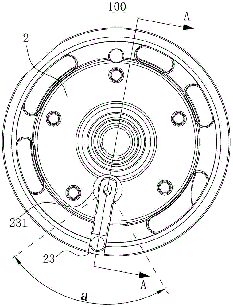
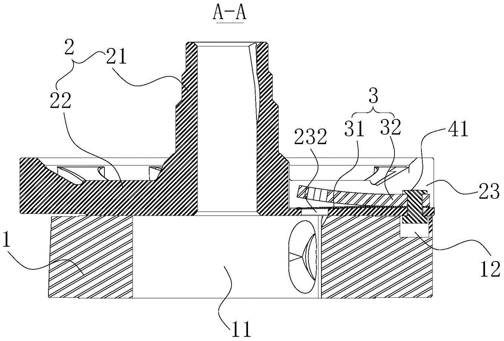
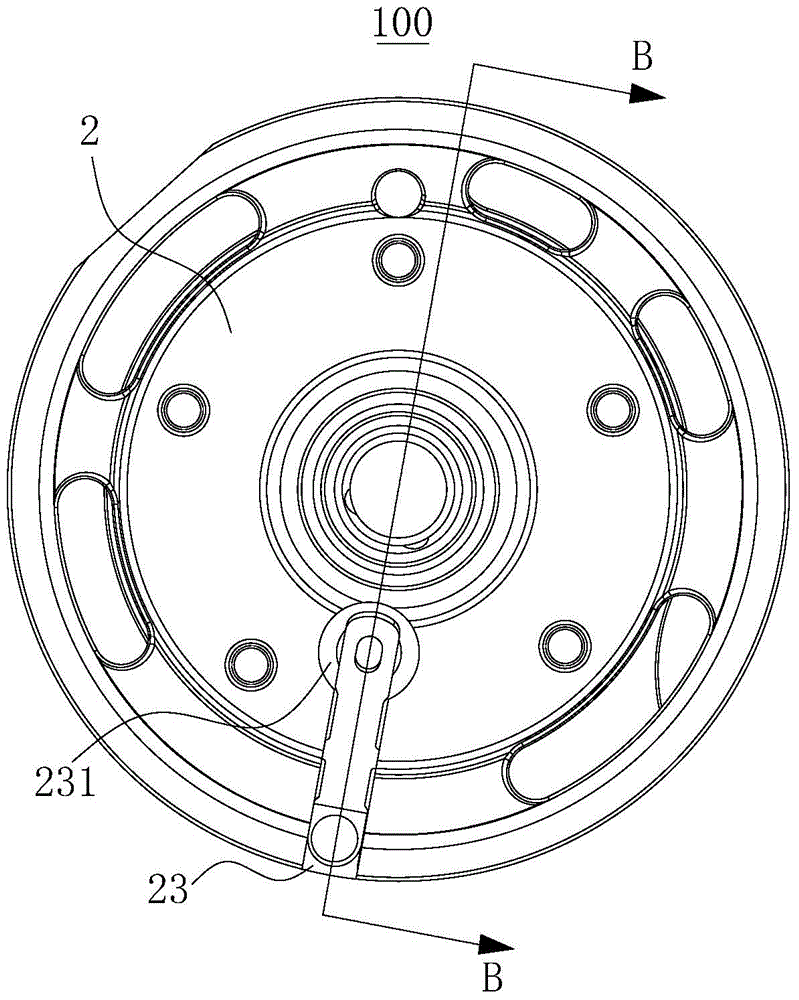
The invention discloses a rotary compressor and a compression mechanism of the rotary compressor. The compression mechanism comprises an air cylinder assembly, a bearing and an exhaust device, wherein the air cylinder assembly comprises an air cylinder, the air cylinder is provided with a compression cavity, a mounting slot is formed in the bearing, a vent hole is formed in the inner wall of the mounting slot and is communicated with the compression cavity, the mounting slot is formed in a sector-shaped area formed by the fact that a reference line takes the center of the vent hole as a rotation center and rotates towards the two sides at a preset angle respectively, the preset angle is 45 degrees, and the reference line is a connection line between the center of the bearing and the center of the vent hole; the exhaust device is arranged in the mounting slot and comprises an exhaust valve plate, and one end of the exhaust valve plate covers the vent hole. According to the compression mechanism, the rigidity of the bearing is improved; when the compression mechanism is applied to the rotary compressor, the radial displacement of a rotor of a motor, caused by magnetic pull force, can be reduced, the abrasion of a crankshaft can be reduced, and meanwhile, the axial displacement, caused by the interference fit of a muffler and the operation temperature rise of the rotary compressor, of the end surface of the bearing is reduced.

Description

technical field [0001] The invention relates to the technical field of compressor manufacturing, in particular to a compression mechanism for a rotary compressor and a rotary compressor with the same. Background technique [0002] It is pointed out in the related art that during the operation of the rotary compressor, the low-pressure gas refrigerant in the cylinder is compressed into a high-pressure gas refrigerant, which is discharged out of the cylinder through the exhaust valve plate and the muffler installed on the bearing assembly groove. Among them, in order to facilitate the exhaust, the volume of the slot at the vent hole can be enlarged, so that the vent hole is generally set in a trapezoidal or slope shape. However, the existing way of slotting the assembly slot weakens the rigidity of the compression mechanism. [0003] Moreover, in the motor, the uneven air gap between the stator and the rotor causes an unbalanced magnetic pull between the two. At this time, if ...

Claims


Application Information

Patent Timeline
Patent Type & Authority Applications(China)
IPC IPC(8): F04C29/00F04C29/12
CPCF04C29/124F04C2240/50
Inventor 吴灏张诚虞阳波
Owner GUANGDONG MEIZHI COMPRESSOR
Why Eureka
Eureka Blog
Learn More