A leak-stopping method for concrete dam gaps
A plugging method and technology of concrete dams, which are applied in water conservancy projects, sea area projects, buildings, etc., can solve the problems of water storage loss, difficulty in penetrating deep, and inability to achieve plugging effects, etc., and achieve good fluidity and strong applicability Effect
- Summary
- Abstract
- Description
- Claims
- Application Information
AI Technical Summary
Problems solved by technology
Method used
Image
Examples
Embodiment 1
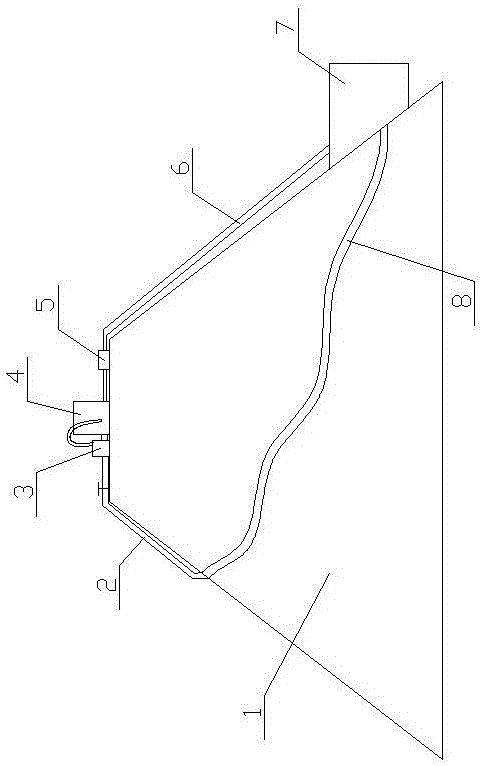
[0031] Embodiment 1, a kind of plugging method of concrete dam gap, such as figure 1 As shown, when the seepage joint 8 of the concrete dam 1 is linear, it runs through from one side of the concrete dam 1 to the other side. The plugging method at this time is that the method uses a plugging device, and the plugging device includes a plugging liquid storage tank 4, an aerator 3 and a plugging liquid collection tank 7, and the air diffuser of the aerator 3 The impeller is set in the plugging liquid storage tank 4, one side of the plugging liquid storage tank 4 is provided with a discharge pipe 2, and the other side is provided with a recovery pipe 6 communicating with the leakage plugging liquid collection tank 7, and the discharge pipe 2 is equipped with a liquid discharge valve, and the recovery pipe 6 is equipped with a recovery pump 5; during plugging operation: place the plugging liquid storage tank 4 on the top of the dam, and place the plugging liquid collection pool 7 at...
Embodiment 2
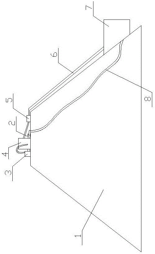
[0032] Embodiment 2, a kind of plugging method of concrete dam gap, such as figure 2 As shown, when the seepage joint 8 of the concrete dam 1 is linear, it penetrates from the top of the concrete dam 1 to the bottom of the dam. The plugging method at this time is that the method uses a plugging device, and the plugging device includes a plugging liquid storage tank 4, an aerator 3 and a plugging liquid collection tank 7, and the air diffuser of the aerator 3 The impeller is set in the plugging liquid storage tank 4, one side of the plugging liquid storage tank 4 is provided with a discharge pipe 2, and the other side is provided with a recovery pipe 6 communicating with the plugging liquid collection tank 7, and the discharge pipe 2 is equipped with a drain valve, and the recovery pipe 6 is equipped with a recovery pump 5; during plugging operation: place the aerator 3 and the plugging liquid storage tank 4 at the highest point of the leakage joint 8, and place the plugging l...
Embodiment 3
[0033] Embodiment 3, as the method described in Embodiment 1 and 2, the volume of the plugging liquid in the plugging liquid storage tank is 0.5 to 1 hour seepage joint flow rate; the volume of the plugging liquid collection tank 7 is 5 ~ 10 minutes leaking seam flow.
PUM
 Abstract
Description
Claims
Application Information
 - R&D
- Intellectual Property
- Life Sciences
- Materials
- Tech Scout
- Unparalleled Data Quality
- Higher Quality Content
- 60% Fewer Hallucinations
Browse by: Latest US Patents, China's latest patents, Technical Efficacy Thesaurus, Application Domain, Technology Topic, Popular Technical Reports.
© 2025 PatSnap. All rights reserved.Legal|Privacy policy|Modern Slavery Act Transparency Statement|Sitemap|About US| Contact US: help@patsnap.com


