
Five-axis machining center coordinate system determination method based on 7-point detection repetition

A technology for machining centers and determining methods, applied in metal processing equipment, metal processing machinery parts, manufacturing tools, etc., can solve problems such as time-consuming and labor-intensive, unguaranteed parts processing quality, and low parts processing efficiency

Inactive Publication Date: 2015-04-01
SHENYANG LIMING AERO-ENGINE GROUP CORPORATION
View PDF8 Cites 12 Cited by
  • Summary
  • Abstract
  • Description
  • Claims
  • Application Information

AI Technical Summary

Problems solved by technology

[0002] At present, the traditional method of determining the five-coordinate machining center requires manual alignment after the workpiece is clamped and clamped. Every time the operator processes a new part, it is necessary to manually align and add the dots of the work mark. Time-consuming and labor-intensive, and the quality is biased towards the operator's processing methods and experience, it will take a lot of time and energy, and the error rate is high, resulting in high labor intensity for processing personnel, low processing efficiency of parts, and the quality of parts processing cannot be guaranteed

Method used


Image

  • Five-axis machining center coordinate system determination method based on 7-point detection repetition
  • Five-axis machining center coordinate system determination method based on 7-point detection repetition
  • Five-axis machining center coordinate system determination method based on 7-point detection repetition

Examples


Embodiment Construction

[0023] An embodiment of the present invention will be further described below in conjunction with the accompanying drawings.

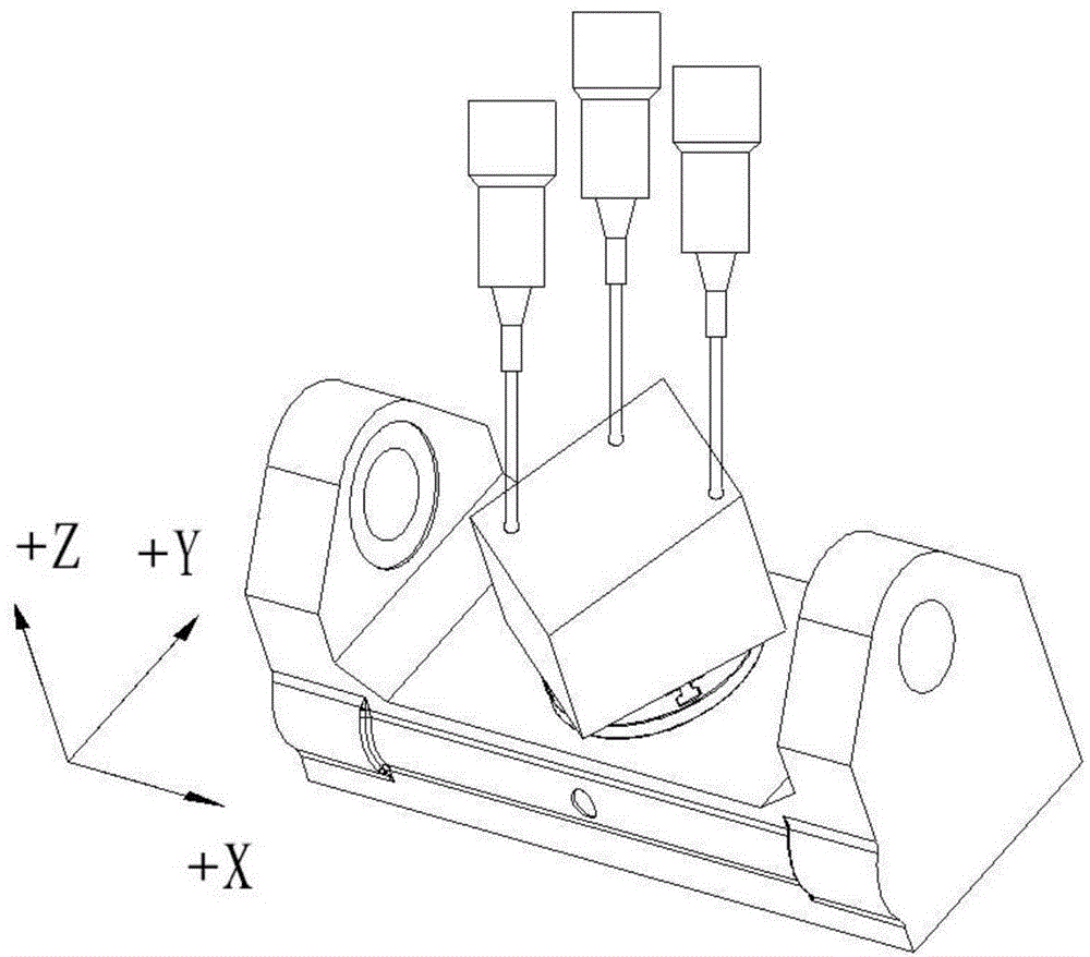
[0024] The invention configures an infrared measuring head in the five-coordinate machining center, uses the infrared measuring head to measure the collision point, and calculates according to the mechanical coordinate data of the collision point to obtain the rotation angle of the fourth axis and the fifth axis of the five-coordinate machining center and the rotation angle of each axis The zero point position is finally automatically input into the origin table or preset table to realize the zero point setting.

[0025] In the embodiment of the present invention, the following content is adopted:

[0026] Five coordinate machining center (Hermle C40u),

[0027] HEIDENHAIN control system (iTNC530);

[0028] 3-point measurement of the probe cycle (TCH PROBE 431MEASURE PLANE),

[0029] 3-point measurement of the probe cycle (TCH PROBE 414DATUM INSIDE ...


PUM


Abstract

The invention discloses a five-axis machining center coordinate system determination method based on 7-point detection repetition and belongs to the field of online measurement of numerical control machining. The five-axis machining center coordinate system determination method based on the 7-point detection repetition changes the traditional manual coordinate system aligning and machining which waste time and labor, and the aligning quality is partial to the processing experience of an operator. The five-axis machining center coordinate system determination method based on the 7-point detection repetition includes that mounting an infrared measuring head at the five-axis machining center, using the infrared measuring head to measure and sample points, calculating according to mechanical coordinate data of the measured points to obtain the rotating angle and zero point position of each of the fourth axis and fifth axis, and writing in a zero point offset table to realize zero point set. The five-axis machining center coordinate system determination method based on the 7-point detection repetition is simple in application conditions and suitable for the five-axis machining center with two rotary axes at a working table; the machining and detection are integrated through reasonably using an online measurement technology, the automatic alignment of the system is effectively realized, the part machining time is shortened, the workload of the operator is reduced, the potential quality hazard due to the alignment of the part machining is avoided, and the non-intervention processing for the part during the whole process is effectively guaranteed.

Description

technical field [0001] The invention belongs to the field of online measurement of numerical control machining, and in particular relates to a method for determining a coordinate system of a five-coordinate machining center based on a seven-point detection cycle. Background technique [0002] At present, the traditional method of determining the five-coordinate machining center requires manual alignment after the workpiece is clamped and clamped. Every time the operator processes a new part, it is necessary to manually align and add the dots of the work mark. It is time-consuming and labor-intensive, and it will take a lot of time and energy to find out the quality of the processing methods and experience of the operator, and the error rate is high, resulting in high labor intensity for the processing personnel, low processing efficiency of the parts, and the quality of the processing of the parts cannot be guaranteed. Contents of the invention [0003] Aiming at the short...

Claims


Application Information

Patent Timeline
IPC IPC(8): B23Q17/24
CPCB23Q17/2428
Inventor 李海泳刘德生范吉平张文明
Owner SHENYANG LIMING AERO-ENGINE GROUP CORPORATION
Learn More