
Cutting and flaring positioning plate

A positioning plate and positioning hole technology, applied in positioning devices, metal processing equipment, feeding devices, etc., can solve the problems of thickening and curling of the upper end of the side, and achieve the effect of uniform thickness of the side, good verticality and wide application

Inactive Publication Date: 2015-04-01
WUZHONG DISTRICT GUANGFU LIANGSHENG MACHINERY FACTORY
View PDF5 Cites 0 Cited by
  • Summary
  • Abstract
  • Description
  • Claims
  • Application Information

AI Technical Summary

Problems solved by technology

During the bottom-cutting process of the frame-shaped cage, the bottom-cutting die is used on the machine tool to cut off the plum blossom print and the remaining material ejected during the punching process. However, due to the structural problems of the bottom-cut positioning plate in the prior art, It is easy to cause the upper end of the side of the frame cage to become thicker when it is formed, or to curl up

Method used


Image

  • Cutting and flaring positioning plate
  • Cutting and flaring positioning plate

Examples


Embodiment Construction

[0013] The present invention is described below in conjunction with accompanying drawing.

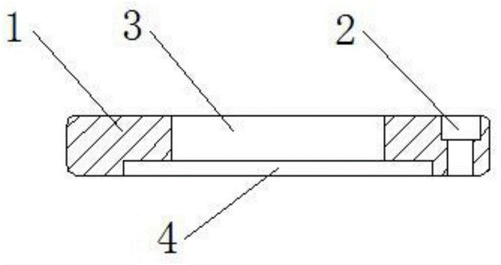
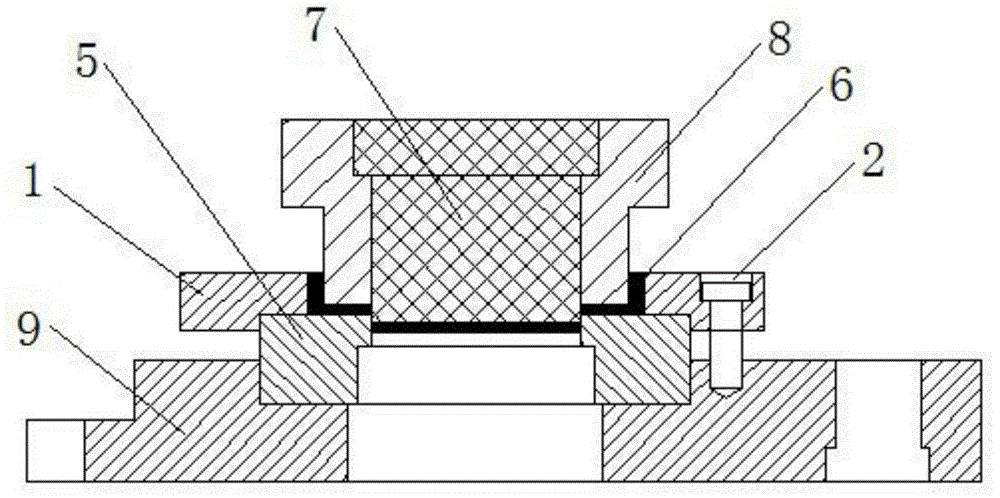
[0014] as attached figure 1 , 2 As shown, the cutting and expanding positioning plate of the present invention is used on the cutting and expanding mold, and the cutting and expanding mold can combine the two processes of bottom cutting and expansion of the frame-shaped cage into one process, and will mainly include a cylindrical plate body 1; the center of the plate body 1 is provided with a positioning hole; the plate body 1 is also provided with at least three bolt through holes 2; the positioning hole is a stepped hole; the positioning hole is divided into a cage forming hole 3 and the die fixing hole 4; the inner diameter of the cage forming hole 3 is equal to the outer diameter of the frame cage 6; the vertical height of the cage forming hole 3 is equal to the height of the frame cage 6.

[0015] Further explanation, the vertical height ratio of the cage forming hole 3 and the d...


PUM


Abstract

The invention discloses a cutting and flaring positioning plate. According to the cutting and flaring positioning plate, the center of a plate body is provided with a positioning hole; the plate body is also provide with at least three bolt through holes; the positioning hole is a stepping hole and is composed of a cage forming hole and a concave die fixing hole; the internal diameter of the cage forming hole is equal to the external diameter of a finished frame-shaped cage; the vertical height of the cage forming hole is higher than the panel height of the finished frame-shaped cage. The cutting and flaring positioning plate is simple in structure and reasonable in design, and by means of structural improvement, solves the problem of thickening or crimping of the upper ends of side surfaces during forming of a frame-shaped cage in the prior art and enables the frame-shaped cage to be uniform in thickness of the side surface and high in verticality during a cutting and flaring forming process, thereby obtaining obvious economic benefits and having a wide application prospect.

Description

technical field [0001] The invention relates to a structure of a positioning plate, in particular to a cutting and expanding positioning plate which can make the side thickness of the frame-shaped cage uniform and good in verticality when the frame-shaped cage is formed in the cutting and expanding process. Background technique [0002] The frame-shaped cage is generally machined according to the process of material cutting, bottom cutting, punching, primary slope, edge cutting, bottom cutting, and expansion. During the bottom-cutting process of the frame-shaped cage, the bottom-cutting die is used on the machine tool to cut off the plum blossom print and the remaining material ejected during the punching process. However, due to the structural problems of the bottom-cut positioning plate in the prior art, It is easy to cause the upper end of the side to become thicker when the frame-shaped cage is formed, or curling occurs. Contents of the invention [0003] In view of t...

Claims


Application Information

Patent Timeline
Patent Type & Authority Applications(China)
IPC IPC(8): B21D43/00
CPCB21D43/003
Inventor 俞玉良
Owner WUZHONG DISTRICT GUANGFU LIANGSHENG MACHINERY FACTORY
Learn More