Alignment method and equipment for thick shaft parts
A technology of straightening and parts, applied in the field of straightening after forging or heat treatment of thick shaft parts, can solve the problems of complex straightening process, low production efficiency, large straightening deformation and springback, and achieve high straightening efficiency. , reduce equipment costs, reduce the effect of rebound
- Summary
- Abstract
- Description
- Claims
- Application Information
AI Technical Summary
Problems solved by technology
Method used
Image
Examples
Embodiment 1
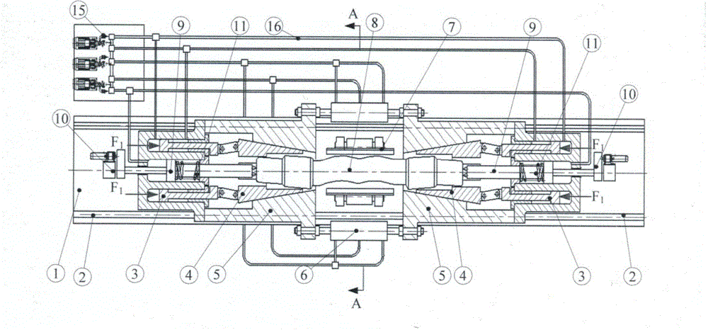
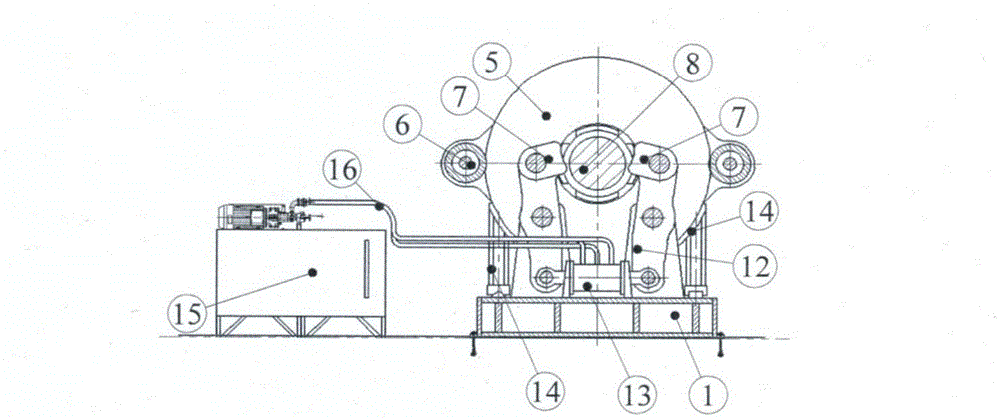
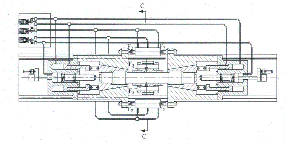
[0028] exist figure 1 , image 3 and Image 6 , Figure 7In the front sectional schematic diagram of a straightening device for thick shaft parts shown, the frame mainly includes a base 1 , a bracket 14 , and a guide rail 2 . The base is fixed on the ground through anchor bolts, the guide rails are laid on both sides of the upper surface of the base, the brackets on both sides are installed on the base through the guide rails, and the brackets on both sides are connected with the clamping mechanism. The clamping mechanism mainly includes an annular oil cylinder 3, a chuck 5 and a movable wedge 4, which are respectively fixed on the two side supports on the guide rail. The chuck is a cylinder with a cavity inside, and a tapered through hole corresponding to the guide rail is provided on the cylinder, and the small diameter holes of the two chucks are installed opposite to each other, and the outer surface of the two chucks is axially opposite. Lugs. In the tapered cavity o...
Embodiment 2
[0030] Take a certain train axle as an example in conjunction with the accompanying drawings for detailed description: please refer to figure 1 , figure 2 , according to the specifications of the train axle 8 to be straightened, select the movable wedge 4 corresponding to the train axle shaft head and the axle seat and the split reverse bending straightening mold 7 equal to the diameter of the axle body; adjust the expansion and contraction of the hydraulic cylinder A6, Make the moving distance of chuck 5 satisfy the length requirement of train axle 8. Open the hydraulic cylinder A6 to push the chuck 5, the annular oil cylinder 3, the movable wedge 4 and the hydraulic top 9 located in the annular oil cylinder, the rotating mechanism 10 and the spring 11 to move to both sides on the base 1 along the guide rail 2; the train axle 8 passes through The feeding device is sent between the left and right chucks of the straightening equipment, and at the same time, oil is supplied to...
Embodiment 3
[0034] see Image 6 , Figure 7 , taking a polished rod shaft as an example, according to the specifications of the polished rod shaft to be straightened, select a movable wedge 4 with the same diameter as the clamping end of the polished rod shaft and a split-flap reverse bending straightening mold 7 with the same diameter as the shaft body; adjust the hydraulic cylinder A6 The amount of expansion and contraction makes the moving distance of the chuck 5 meet the length needs of the shaft. After the adjustment, the straightening method of the polished rod shaft is the same as the straightening method of the train shaft in embodiment 2, please refer to embodiment 2.
PUM
 Abstract
Description
Claims
Application Information
 - R&D
- Intellectual Property
- Life Sciences
- Materials
- Tech Scout
- Unparalleled Data Quality
- Higher Quality Content
- 60% Fewer Hallucinations
Browse by: Latest US Patents, China's latest patents, Technical Efficacy Thesaurus, Application Domain, Technology Topic, Popular Technical Reports.
© 2025 PatSnap. All rights reserved.Legal|Privacy policy|Modern Slavery Act Transparency Statement|Sitemap|About US| Contact US: help@patsnap.com


