A device for collecting condensate at the top of the flue gas deflector of a wet chimney

The technology of collecting device and guide plate is applied in the field of condensate collecting device at the top of flue gas guide plate of wet chimney. The problems such as condensate on the flue gas deflector are not considered, and the effect of avoiding acid mist deposition, highlighting high efficiency and simple structure is achieved.

Active Publication Date: 2016-08-17
SHANGHAI DEFOG ENVIRONMENTAL SCI & TECH
View PDF8 Cites 4 Cited by
  • Summary
  • Abstract
  • Description
  • Claims
  • Application Information

AI Technical Summary

Problems solved by technology

[0010] The structure of the chimney inlet is relatively complicated, especially after the flue gas deflector is installed, due to the narrowing of the flow space, the flue gas flow rate in this area increases rapidly, and eddy currents are prone to occur, which will cause the condensate to be entrained by the flue gas and discharged to the atmosphere In the environment, the entrained condensate droplets are usually large in size, and they are the main cause of "chimney rain" or acid mist deposition
[0011] At present, most of the conventional wet chimney structure designs do not consider the humid environment where eddy currents will occur in the area of ​​the flue gas deflector and are prone to condensation, nor do they consider installing a condensate collection device on the flue gas deflector to collect the condensate generated, so that Unavoidable vortex phenomenon and secondary entrainment of condensate

Method used


Image

  • A device for collecting condensate at the top of the flue gas deflector of a wet chimney
  • A device for collecting condensate at the top of the flue gas deflector of a wet chimney
  • A device for collecting condensate at the top of the flue gas deflector of a wet chimney

Examples


Embodiment 1

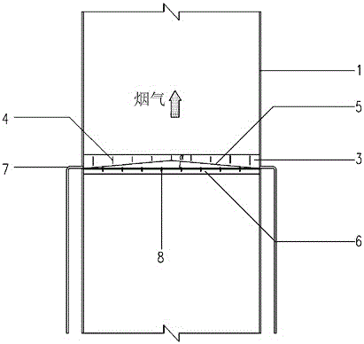
[0048] refer to Figure 1-3 The condensate collecting device at the top of the wet chimney flue gas deflector provided by the present invention includes a fixed bracket 6 and a collecting tank 3, and the collecting tank 3 is arranged along the top of the flue gas deflector 9 through the fixing bracket 6; certainly the collecting tank 3 also It can be directly arranged on the top of the deflector 9 without installing through the fixing bracket 6, and there is no limitation here. The fixed bracket 6 can be fixed with the flue gas guide plate 9 by means of welding or the like, and the collection tank 3 can be connected with the fixed bracket 6 by means of high-strength bolts 8 or welding. Of course, this is only an implementation mode. The flue gas guide The plate 9, the fixed bracket 6, and the collection tank 3 can also be connected by other connection methods, which are not limited here.

[0049] In this embodiment, the length of the fixed bracket 6 and the collection tank 3 ...

Embodiment 2

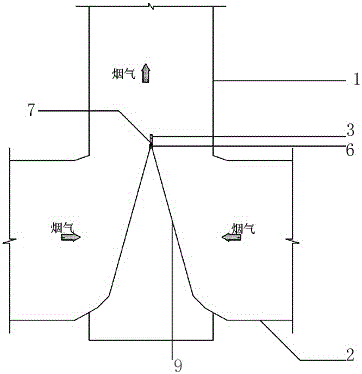
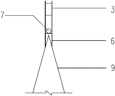
[0056] refer to Figure 4-6 , the wet chimney flue gas deflector top condensate collecting device provided by the present invention comprises a fixed bracket 6 and a collection tank 3, and the collection tank 3 is arranged along the top of the smoke deflector 9 through the fixed bracket 6; A notch is provided on the side, and a water guide plate 5 and a reinforcing plate 4 are arranged in the notch, and a drainage hole and a drainpipe 7 are arranged at the lowest position in the notch.

[0057] In this embodiment, two water guide plates 5 are arranged in the notches on both sides of the collection tank 3, and the two water guide plates 5 are respectively inclined downward from the two ends of the notch to the middle, and the two water guide plates 5 are in the shape of "V" shape; at this time, the middle position of the collection tank 3 is the lowest position, and the middle position of the collection tank 3 is provided with a drain port and a drain pipe 7; condensate is coll...

Embodiment 3

[0060] The device for collecting condensate at the top of the flue gas deflector of the wet chimney provided by the present invention comprises a fixed bracket 6 and a collecting tank 3, and the collecting tank 3 is arranged along the top of the flue gas deflector 9 through the fixing bracket 6; both sides of the collecting tank 3 A notch is arranged on the top, and a reinforcing plate 4 is arranged in the notch, and a drainage hole is opened at the lowest position of the notch and a drainpipe 7 is arranged.

[0061] In this embodiment, the bottoms of the notches on both sides of the collection tank 3 are designed in a "V" or inverted "V" shape; Set at the lowest position in the middle of the bottom of the collecting tank 3; when the bottom of the notch of the collecting tank 3 is in an inverted "V" shape, the lowest positions at both ends of the bottom of the collecting tank 3 are respectively provided with drains and drain pipes 7.

[0062] The difference between this embodi...


PUM


Abstract

The utility model provides a condensed fluid collection device at the top end of a wet chimney smoke guide plate. The condensed fluid collection device comprises a fixed support and a collecting tank, wherein the collecting tank is installed on the top end of a wet chimney smoke guide plate through the fixed support. Notches are formed in two sides of the collecting tank, a water discharging hole is formed in the lowest position in each notch, and a water discharging pipe is arranged in the water discharging hole; a reinforcing plate and a water guide plate are arranged inside the collecting tank, the water guide plate is used for guiding the collected condensed fluid to the water discharging pipe and discharging the condensed fluid out of a chimney. A smoke field in a smoke guide plate area in an inlet of the chimney is relatively complicated, the secondary entrainment phenomenon of the condensed fluid is likely to happen, the collecting device is arranged on the guide plate, the vortex generated nearby the smoke guide plate can be effectively eliminated, and the generated condensed fluid can be collected and discharged out of the chimney, so that the stack rain phenomenon caused by the secondary entrainment of the condensed fluid entering the atmosphere can be effectively avoided; meanwhile, the condensed fluid collection device is reliable, high efficient, economical, practical and easy to realize.

Description

technical field [0001] The invention relates to the technical field of chimney design, in particular to a device for collecting condensate at the top of a wet chimney flue gas guide plate, which is used for the treatment of wet chimney "chimney rain" phenomenon in thermal power plants, chemical industry, metallurgy and other industries adopting wet desulfurization technology . Background technique [0002] The limestone-gypsum wet flue gas desulfurization process is the most widely used and mature process in the world today, and it is also the leading process for desulfurization of domestic thermal power plants. More than 90% of thermal power units above 300MW in my country adopt limestone-gypsum wet flue gas desulfurization (WFGD) technology. Desulfurization Design Technical Regulations (DL / T5196-2004) stipulates that "under design conditions, the flue gas temperature at the chimney inlet after desulfurization should generally reach 80°C or higher for discharge", so the WFG...

Claims


Application Information

Patent Timeline
Patent Type & Authority Patents(China)
IPC IPC(8): B01D45/06B01D45/18
CPCB01D45/06B01D45/18B01D2221/16
Inventor 戴永阳靳庆新吴永杰
Owner SHANGHAI DEFOG ENVIRONMENTAL SCI & TECH
Why Eureka
Try Eureka