
System for charge air cooling and associated method for providing charge air cooling for an internal combustion engine

A charge air cooling and charge air technology, applied in the field of providing charge air cooling and motor vehicles, can solve the problems of insufficient intake pipes integrated with charge air coolers, inability to use common intake pipes, high cost, etc. , to achieve the effect of rapid response, small pressure loss and small volume

Inactive Publication Date: 2015-03-25
BEHR GMBH & CO KG
View PDF6 Cites 0 Cited by
  • Summary
  • Abstract
  • Description
  • Claims
  • Application Information

AI Technical Summary

Problems solved by technology

[0004] However, such a cascaded charge air cooling system with two coolers (HT cooler and NT cooler) integrated in the intake duct is an expensive application because it has to be developed especially for top-of-the-range engines and due to With regard to requirements in terms of construction space and dead volume to be avoided, intake ducts for low-level engines may not be able to be used together
[0005] In addition, the combination of high charge pressure and high engine temperature with high charge has the following consequences: the partial throttle valve must be cooled and the plastic material is too heavy for the intake manifold with integrated charge air cooler due to its strength. Saying is not enough, and aluminum intake pipes must therefore be used
All in all, this results in higher costs

Method used


Image

  • System for charge air cooling and associated method for providing charge air cooling for an internal combustion engine
  • System for charge air cooling and associated method for providing charge air cooling for an internal combustion engine
  • System for charge air cooling and associated method for providing charge air cooling for an internal combustion engine

Examples


Embodiment Construction

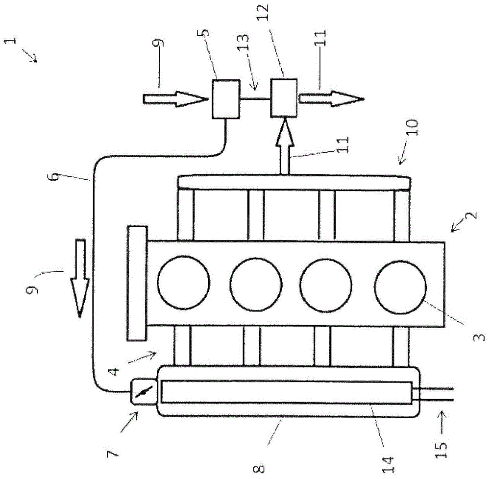
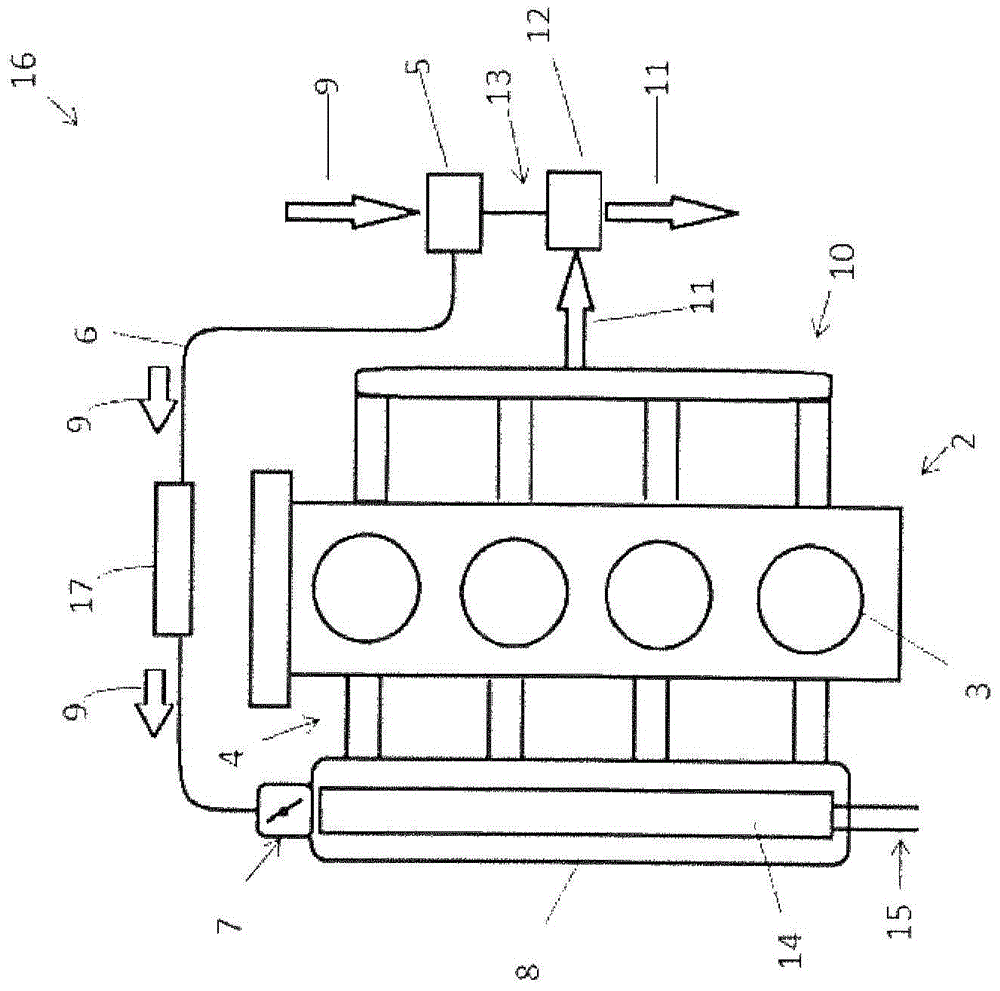
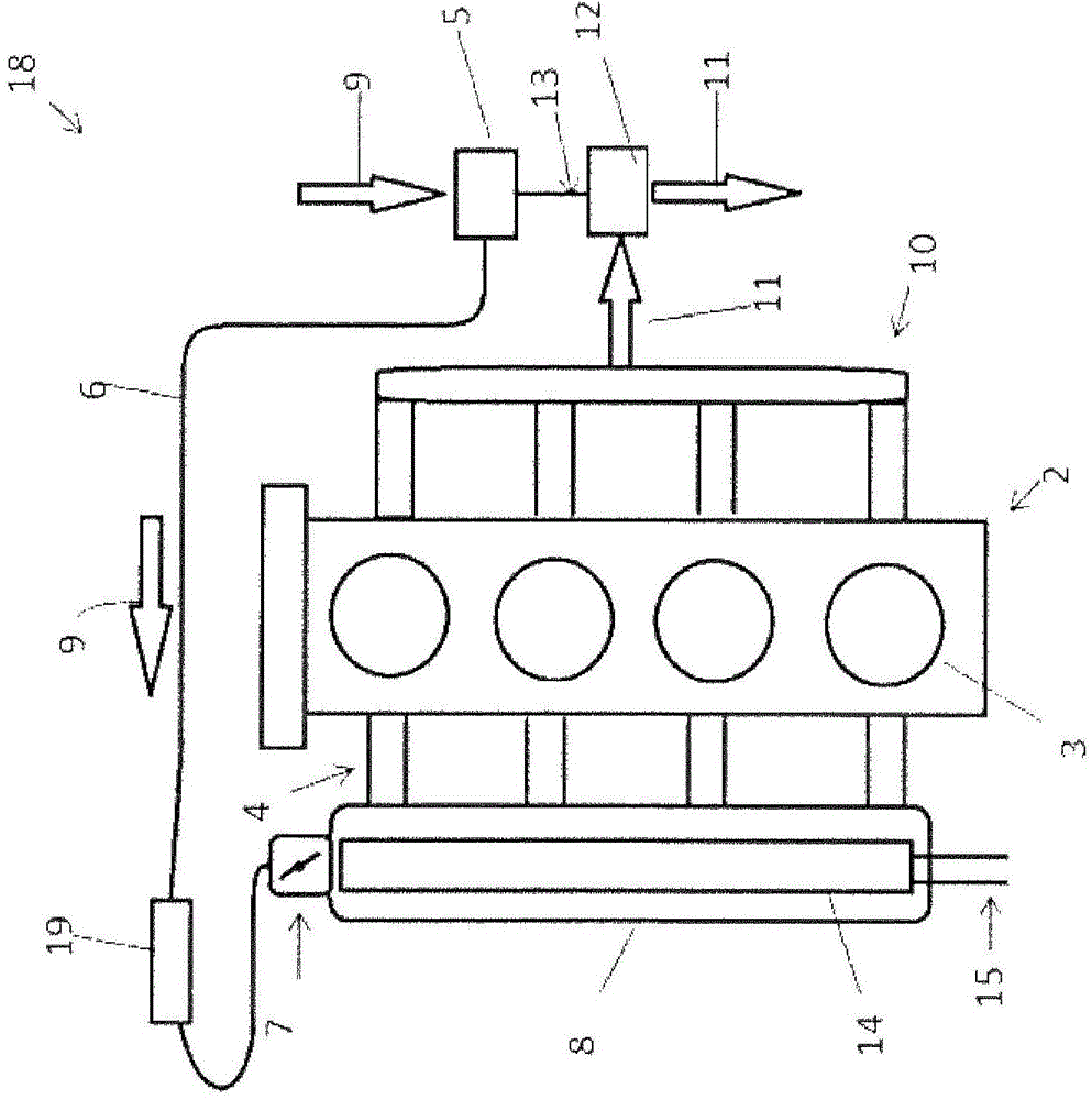
[0032]FIG. 1 shows a first embodiment of an arrangement 1 of an internal combustion engine 2 according to the invention with a charge air cooling device according to the basic solution aspect of the invention. Internal combustion engine 2 here includes four cylinders or four combustion chambers 3 . The combustion chamber 3 is supplied with intake air via an intake manifold. In FIG. 1 , the intake manifold is denoted by reference numeral 4 . The internal combustion engine is connected to a charge air compressor 5 . After compression, the charge air is conveyed further by means of a charge air line 6 and supplied via a throttle valve 7 to an intake manifold 8 upstream of the intake manifold 4 . The flow of charge air or intake air in the intake manifold is marked with arrow 9 in FIG. 1 . After combustion, the exhaust gases are routed to a turbocharger turbine 12 through an exhaust system 10 consisting of an exhaust pipe and an exhaust manifold. The exhaust gas flow is likewi...


PUM


Abstract

The invention relates to a system for charge air cooling for an internal combustion engine (2) based on an engine family, wherein an intake module (8) is arranged between a throttle valve (7) and a combustion chamber (3). A first cooling device (14) of the system is shaped to be structurally integrated into the intake module (8). Furthermore, in accordance with the system, a second cooling device (17, 19) is available, which supplements the first cooling device (14) and which is designed to pre-cool charge air before said charge air enters the intake module (8) and which is adapted for use with at least one engine model of the engine family. The second cooling device is intended for top engine types and can be arranged between the throttle valve (7) and a charge air compressor (5).

Description

technical field [0001] The invention relates to a charge air cooling system for an internal combustion engine based on an engine family according to the preamble of claim 1 . Furthermore, the invention relates to a corresponding method for providing charge air cooling according to the preamble of claim 7 . Furthermore, the invention relates to an internal combustion engine with a charge air compression device and a motor vehicle with an internal combustion engine. Background technique [0002] Component standardization is increasingly important in today's vehicle and engine families. Therefore, especially for the charge air cooling of the individual engine variants or engine types, as far as possible identical charge air coolers must be used, but these charge air coolers must cover a wide range of thermal performances. Especially for top-range engines, such thermal performance can arise for charge air cooling that they can no longer be cooled solely by the low-temperature ...

Claims


Application Information

Patent Timeline
Patent Type & Authority Applications(China)
IPC IPC(8): F02M35/10F02B29/04
CPCF02M35/10268F02B29/0412F02B29/0475F02B29/0406
Inventor 约翰尼斯·蒂姆马克·希内曼马蒂亚斯·菲伦巴赫
Owner BEHR GMBH & CO KG
Learn More