
X-ray device and ct equipment with the same

An X-ray and electron emission technology, which is applied in X-ray equipment, X-ray tube components, X-ray tubes, etc., can solve the problems of complex production process, low carbon nanotube emission ability and lifespan, and improve the target Density, narrow target distribution spacing, and cost reduction effects

Active Publication Date: 2017-08-25
NUCTECH CO LTD +1
View PDF3 Cites 2 Cited by
  • Summary
  • Abstract
  • Description
  • Claims
  • Application Information

AI Technical Summary

Problems solved by technology

However, there are disadvantages such as complex production process, low emissivity and lifespan of carbon nanotubes

Method used


Image

  • X-ray device and ct equipment with the same
  • X-ray device and ct equipment with the same
  • X-ray device and ct equipment with the same

Examples


Embodiment

[0092] (system composition)

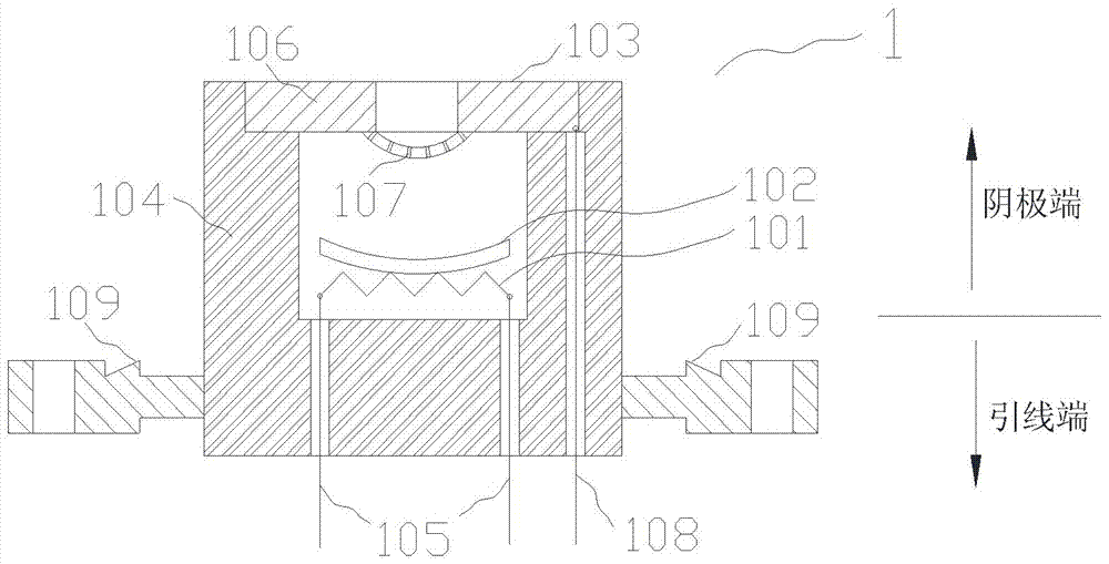
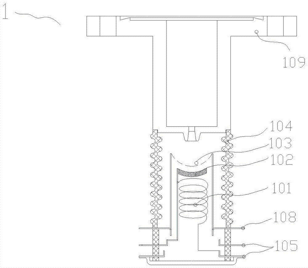
[0093] Such as Figure 1 to Figure 6As shown, the two-dimensional distributed X-ray device consists of a plurality of electron emission units 1, an anode 2, a vacuum box 3, a high-voltage power supply connection device 4, a filament power supply connection device 5, a grid control device connection device 6, a vacuum device 8, and The power supply and control system consists of 7 components. A plurality of electron emission units 1 are arranged on a plane in a two-dimensional arrangement, and are installed on the box wall of the vacuum box 3, each electron emission unit 1 is independent of each other, and the strip-shaped anode 2 is located in the electron emission unit 1 above, installed on the upper end of the vacuum box 3, parallel to the plane where the electron emission unit 1 is located. The electron emission unit 1 includes a filament 101 , a cathode 102 , a grid 103 , an insulating support 104 , a filament lead 105 and a connecting fixtu...


PUM


Abstract

The two-dimensional array distributed X-ray device of the present invention comprises: a vacuum box sealed around and a high vacuum inside; a plurality of electron emission units arranged on a plane in a two-dimensional arrangement on the box wall of the vacuum box; an anode , with targets corresponding to a plurality of electron emission units, arranged in a vacuum box parallel to the plane where the plurality of electron emission units are located; power supply and control system, with a high-voltage power supply connected to the anode, and a plurality of electron emission units A filament power supply connected to each of the multiple electron emission units, a grid control device connected to each of the plurality of electron emission units, a control system for controlling each power supply, the anode includes: an anode plate, made of a metal material and connected to the electron emission The upper surfaces of the units are parallel; a plurality of targets, mounted on the anode plate and arranged in a manner respectively corresponding to the positions of the electron emission units, the bottom surfaces of the targets are connected with the anode plate and the top surfaces form a predetermined angle with the anode plate.

Description

technical field [0001] The present invention relates to a device for generating distributed X-rays, in particular to two-dimensionally arranging a plurality of independent electron emission units and arranging a plurality of corresponding targets on the anode in an X-ray light source device and controlling the cathode or grid A two-dimensional array distributed X-ray for generating X-rays whose focus positions are changed in a predetermined order and a CT device with the X-ray device. Background technique [0002] Generally speaking, an X-ray light source refers to equipment that generates X-rays, usually consisting of X-ray tubes, power supply and control systems, auxiliary devices such as cooling and shielding, etc., and its core is the X-ray tube. X-ray tubes usually consist of a cathode, an anode, and a glass or ceramic housing. The cathode is a direct-heated spiral tungsten wire. When it is working, it is heated to a high temperature state by passing an electric curren...

Claims


Application Information

Patent Timeline
Patent Type & Authority Patents(China)
IPC IPC(8): H05G1/30H01J35/06H01J35/08
CPCH01J35/02H01J2235/068H01J2235/086H01J35/064H01J35/066H01J35/116H01J35/147G21K1/087H01J35/025H01J35/045H01J35/10H01J2235/062H01J35/153G21K1/08
Inventor 唐华平唐传祥陈怀璧黄文会张化一郑曙昕刘晋升
Owner NUCTECH CO LTD
Learn More