Power supply protection device

A power supply protection and charging power supply technology, which is applied in the direction of circuit devices, battery circuit devices, DC network circuit devices, etc., can solve the problems of voltage drop in the charging circuit, failure to ensure the safety of the charging process, and failure to meet the charging requirements of the terminal.

Active Publication Date: 2015-03-25
ZTE CORP
View PDF7 Cites 13 Cited by
  • Summary
  • Abstract
  • Description
  • Claims
  • Application Information

AI Technical Summary

Problems solved by technology

but, image 3 In the method shown, when the charging current is large, the forward conduction voltage of the diode will increase, causing the voltage of the charging circuit to decrease, which cannot meet the charging requirements of the terminal and cannot be charged.
[0006] From the above description, it is not difficult to find that the existing methods cannot guarantee the safety of the charging process when the mobile device is under two or more charging paths.

Method used


Image

  • Power supply protection device
  • Power supply protection device
  • Power supply protection device

Examples


Embodiment Construction

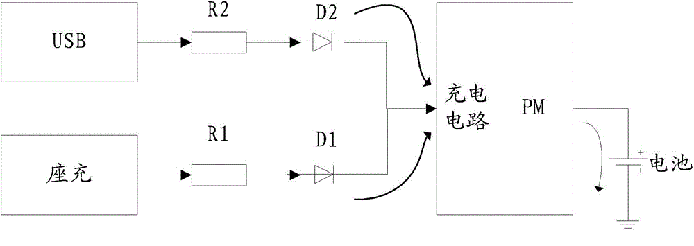
[0025] Figure 4 It is a schematic diagram of the power protection device of the present invention, such as Figure 4 shown, including at least:

[0026] Two or more isolation circuits are connected between each charging power source and the charging circuit to prevent reverse connection of each charging power source;

[0027] The control circuit is connected between the charging source and the isolation circuit, and is used for shutting off the charging path so that only one charging path is charged when two or more charging paths are simultaneously charged.

[0028] Among them, the isolation circuit can be an analog circuit composed of a P-channel field effect transistor (PMOS) and an N-channel field effect transistor (NMOS), or an independently packaged electronic component formed by combining the two. When there is only one charging path , through the NMOS, the PMOS is completely turned on in one direction, so that the isolation circuit has the isolation effect of one-wa...


PUM


Abstract

Disclosed is a power supply protection device. The power supply protection device comprises two or more isolating circuits and a control circuit. The two or more isolating circuits are connected between all charging sources and charging circuits and are used for preventing the inverse connection of all the charging sources. The control circuit is connected between the charging sources and the isolating circuits and is used for disconnecting charging routes to allow only one charging route to conduct charging when two or more charging routers are connected for charging at the same time. According to the power supply protection device, the isolating circuit connected between the charging sources and the charging circuits is used for conducting isolation protection on each charging route, when the number of the charging routes is larger than one, the control circuit is used for conducting judge selection, only one charging route is reserved, and therefore the charging circuits can be protected.

Description

technical field [0001] The invention relates to the field of electronic circuit design, in particular to a power protection device. Background technique [0002] With the widespread use of mobile devices, people put forward higher requirements for their reliability and security. At present, a large number of mobile devices are charged by a factory-configured charger. figure 1 It is a schematic diagram of the existing charger for charging, where the resistor R1 is the line impedance, such as figure 1 As shown, when the terminal needs to be charged, the user plugs the adapter into the charger, and then places the terminal on the charger to connect to the charging circuit and charge. [0003] With the increase of terminal charging paths, for example, the continuous popularization of wireless charging methods, the terminal charging paths will also continue to increase. It is more and more common that two charging paths or multiple charging paths exist at the same time. [00...

Claims


Application Information

Patent Timeline
Patent Type & Authority Applications(China)
IPC IPC(8): H02J7/00
CPCH02J7/0034H02J1/108H02J2207/40
Inventor 宁金星曲廷梁超
Owner ZTE CORP
Why Eureka
Try Eureka