
Intermediate electrical connector

An electrical connector and connector technology, which is applied in the direction of connection, components and circuits of connecting devices, can solve problems such as difficulty, and achieve the effect of simple manufacturing

Active Publication Date: 2015-03-25
HIROSE ELECTRIC GROUP
View PDF4 Cites 16 Cited by
  • Summary
  • Abstract
  • Description
  • Claims
  • Application Information

AI Technical Summary

Problems solved by technology

Therefore, in order to cope with the possible large deviation, it is necessary to ensure that the groove width of the storage groove is sufficiently large correspondingly, and in order to maintain the strength of the housing, it is also necessary to ensure the distance between the end wall of the housing and the storage groove. The thickness dimension of the partition wall between the two leads to the enlargement of the intermediate electrical connector and the connector assembly in the above-mentioned long-side direction
[0008] In addition, as shown in Patent Document 1, accommodating grooves and receiving grooves having groove widths slightly larger than the plate thickness dimension of the intermediate member but not so large are formed in the casing and the target casing at multiple and dense positions, Or it is not easy to form the above-mentioned protrusion in the above-mentioned receiving groove

Method used


Image

  • Intermediate electrical connector
  • Intermediate electrical connector
  • Intermediate electrical connector

Examples


no. 1 approach

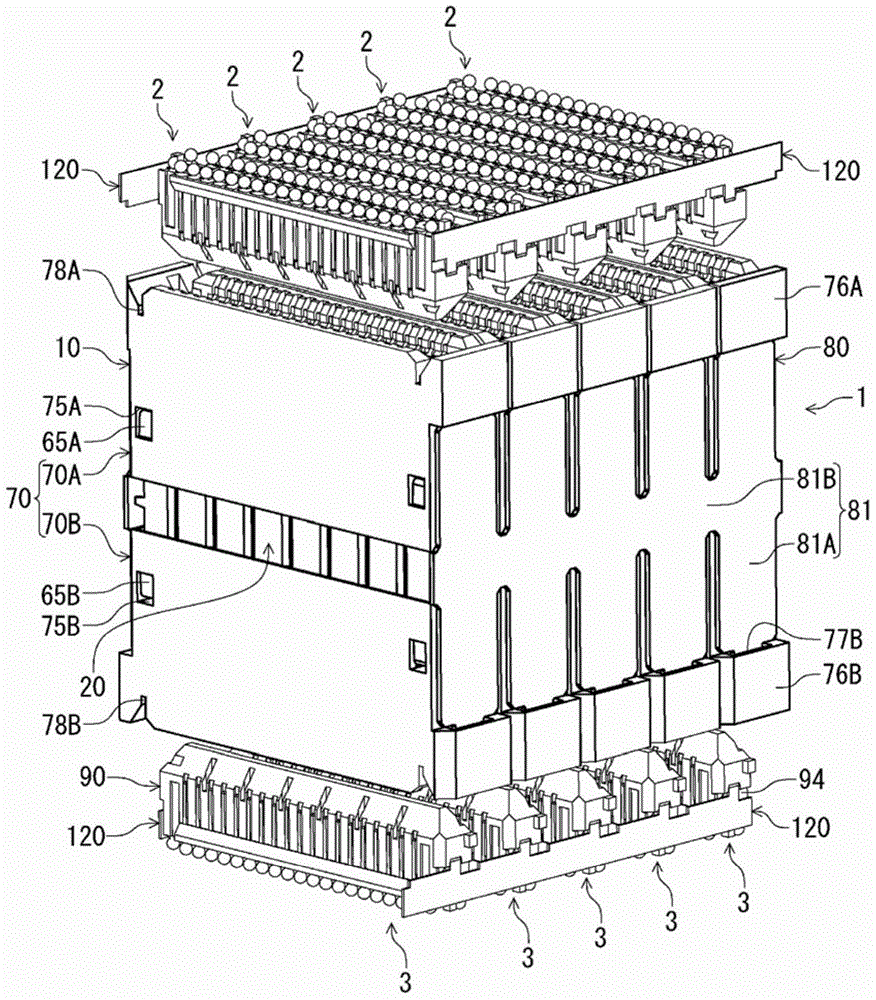
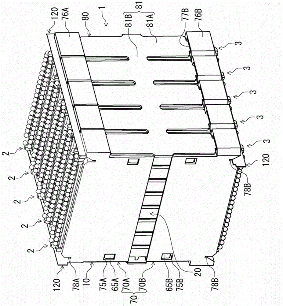
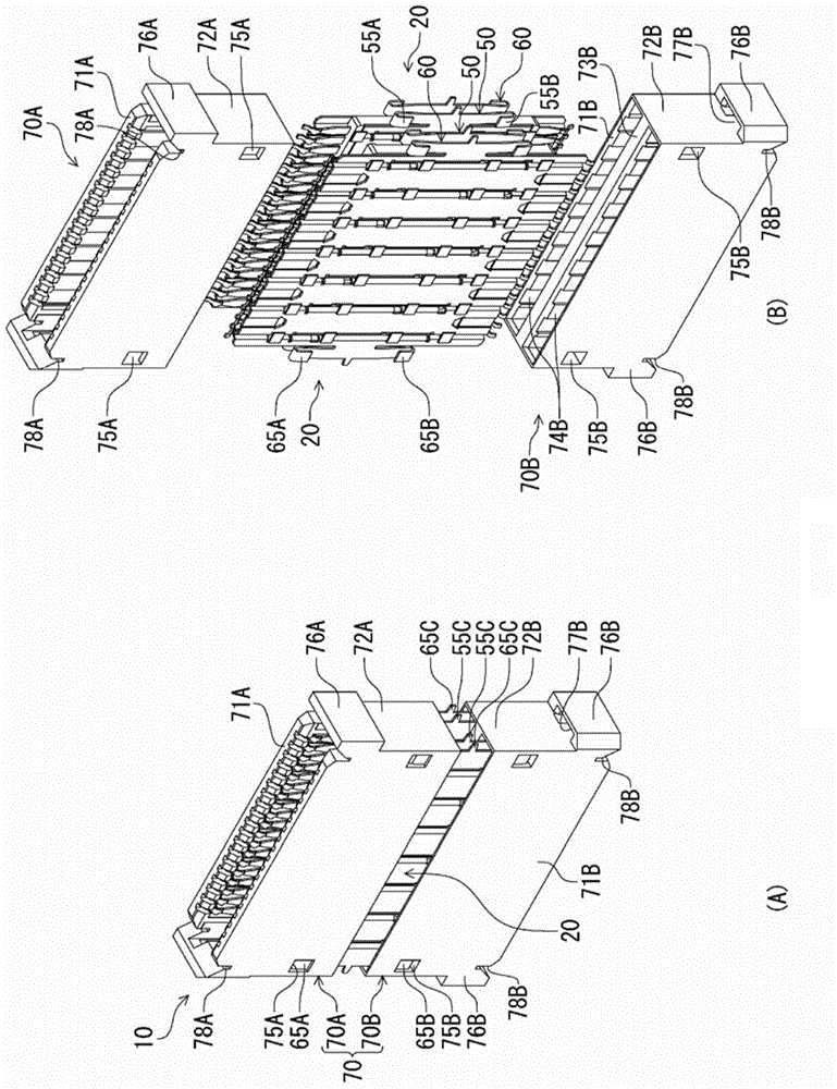
[0056] figure 1 It is a perspective view showing the electrical relay connector and the mating connector according to the first embodiment of the present invention, showing a state before the connectors are fitted. in addition, figure 2 is showing figure 1 A perspective view of the connector mating state of the relay electrical connector and the counterpart connector. A plurality of object connectors 2 and 3 as object connecting bodies are respectively connected to the relay electrical connector 1 of this embodiment (hereinafter simply referred to as "relay connector 1") from above and below, and the two connectors are connected to each other. continue the connection. The aforementioned counterpart connectors 2 and 3 have the same shape as each other, and are electrical connectors for circuit boards respectively connected to different circuit boards (not shown). In this embodiment, from figure 1It can be seen that, in the present embodiment, there are five relay connecti...

no. 2 approach

[0129] Figure 17 It is a perspective view showing the relay electrical connector and the mating connector according to the second embodiment of the present invention, showing a state before the connectors are fitted. in addition, Figure 18 is showing Figure 17 A perspective view of the connector mating state of the relay electrical connector and the counterpart connector. The relay electrical connector 201 of this embodiment (hereinafter simply referred to as "relay connector 201") is respectively connected to a plurality of object connectors 202, 203 as object connecting bodies from above and below, and relays the two connectors to each other. connect. The corresponding connectors 202 and 203 are formed in the same shape as each other, and are electrical connectors for circuit boards respectively connected to different circuit boards (not shown). In this embodiment, from Figure 17 It can be seen that in this embodiment, the four target connectors 202 arranged on one ...


PUM


Abstract

The invention provides an intermediate electrical connector. The intermediate electrical connector will not be enlarged, is capable of deviating along with positions of target connecting bodies and is easy to manufacture. Side faces of two sides of an intermediate body (10) are provided with to-be-supported parts (76A, 76B) supported by a supporting member (80). The supporting member (80) is formed of plate members facing the side surface portion of two sides of the intermediate connecting member. The plate members extend along the arranging direction and upper and lower directions of the intermediate connecting body and are in the arranging scope of the above arranging direction and the above intermediate connecting body. The supporting member includes a supporting portion accommodated in the supported portion or receiving the supported portion with a space in between.

Description

technical field [0001] The present invention relates to a relay electrical connector that uses a target connector or a circuit board as a target connection body and connects two target connection bodies. Background technique [0002] As such a connector, for example, an intermediate electrical connector disclosed in Patent Document 1 as an intermediate electrical connector is known. Patent Document 1 discloses that electrical connectors for circuit boards (target connectors) serving as target connecting bodies are respectively fitted into intermediate electrical connectors from above and below, and that the upper and lower target connectors are electrically connected to each other via the intermediate electrical connectors. connected electrical connector assembly. The above-mentioned intermediate electrical connector includes: a plurality of intermediate members formed in a plate shape and connected to respective connecting bodies; and a case that holds the plurality of int...

Claims


Application Information

Patent Timeline
Patent Type & Authority Applications(China)
IPC IPC(8): H01R31/06H01R13/46
CPCH01R12/91H01R12/73H01R13/518H01R31/06H01R13/46
Inventor 玉井畅洋
Owner HIROSE ELECTRIC GROUP
Learn More