Eureka AIR delivers breakthrough ideas for toughest innovation challenges, trusted by R&D personnel around the world.

A Stiffness Adjustable Device with Thermal Conduction, Electrical Conduction and High Damping Properties

A high damping, stiffness technology

Active Publication Date: 2016-06-01
XIAN INSTITUE OF SPACE RADIO TECH
View PDF5 Cites 0 Cited by
  • Summary
  • Abstract
  • Description
  • Claims
  • Application Information

AI Technical Summary

Problems solved by technology

At present, the common vibration damping devices mainly include rubber shock absorbers, wire shock absorbers, damping layer shock absorbers, air spring shock absorbers, etc. The disadvantage is that although these devices have adopted vibration reduction measures to improve the mechanical environment, they have blocked The thermal conduction path, so that the electronic device cannot meet the thermal design requirements at all; and once the structure is determined, its stiffness cannot be adjusted
However, common adjustable stiffness devices, such as spring adjustment devices and variable cross-section structure stiffness adjustment devices, cannot effectively achieve vibration reduction, and passive devices with both vibration reduction and stiffness adjustment in the same device have not been reported yet.

Method used


Image

  • A Stiffness Adjustable Device with Thermal Conduction, Electrical Conduction and High Damping Properties
  • A Stiffness Adjustable Device with Thermal Conduction, Electrical Conduction and High Damping Properties
  • A Stiffness Adjustable Device with Thermal Conduction, Electrical Conduction and High Damping Properties

Examples


Embodiment

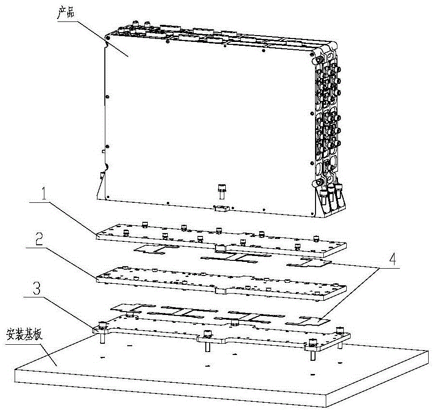
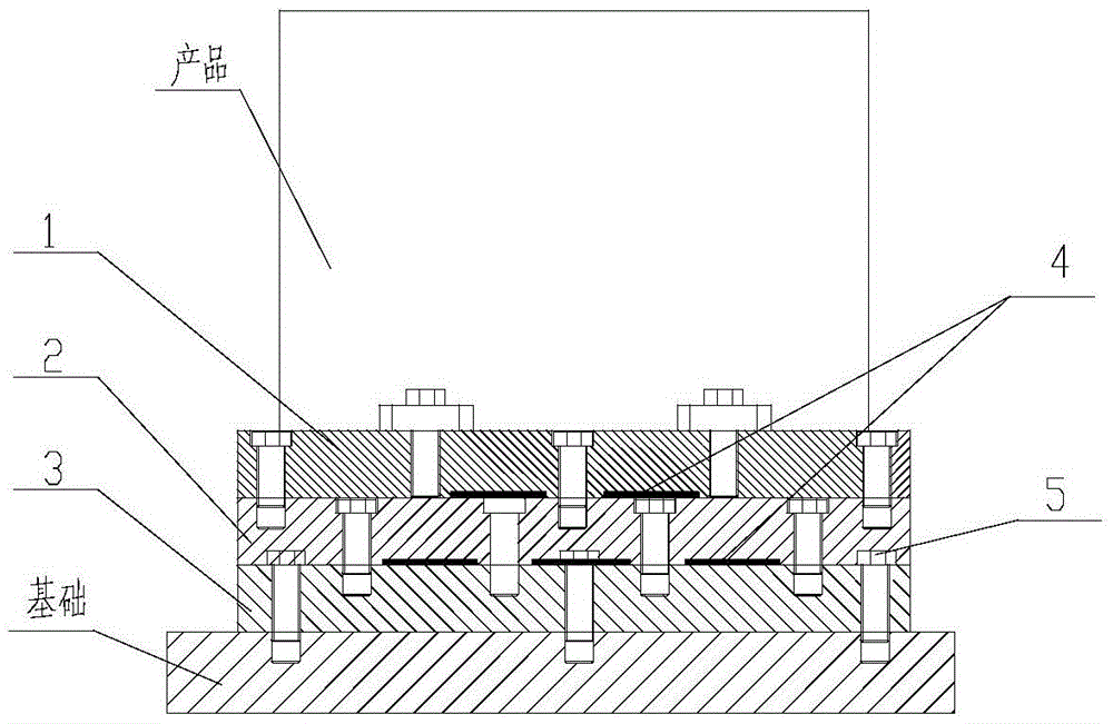
[0042] Taking a space-borne stand-alone machine as the vibration reduction object, the weight of the single machine is 3.5Kg, the vibration isolation plate assembly is composed of 2 layers of vibration isolation plates, the thickness and size of the vibration isolation plate, in order to reduce the weight, the vibration isolation plate is designed to reduce the contact area; 2 A 0.5mm high-damping viscous pad 4 is used in the middle of the vibration isolation plate, which is directly pressed between the two layers of vibration isolation plates. The single machine is connected to the upper vibration isolation plate 1 through 6 M4 screws, and the lower vibration isolation plate 3 is connected to the installation foundation through 4 A M4 screw connection, 3 pairs of screw hole groups were selected for connection between the two vibration isolation plates, and a vibration test was carried out to verify the aspects of heat conduction, electrical conduction, vibration reduction, and ...


PUM


Abstract

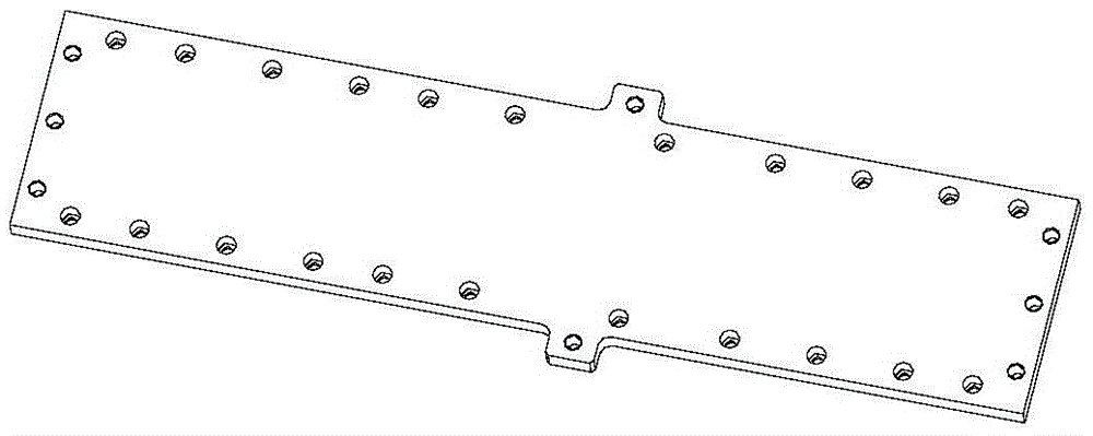
A rigidity-adjustable device with characteristics of heat conduction, electric conduction and high damping comprises a vibration isolation plate assembly, high-damping sticky pads (4) and connecting fasteners (5). The vibration isolation plate assembly is composed of two or more vibration isolation plates which are stacked perpendicularly. The upper vibration isolation plate (1) is provided with a threaded hole group and a stepped hole group. The bottom vibration isolation plate (3) is provided with an unthreaded hole group and a threaded hole group. The upper vibration isolation plate (1) is fixedly connected with a product through threaded holes and the connecting fasteners (5). The bottom vibration isolation plate (3) is fixedly connected with a mounting base plate through unthreaded holes and the connecting fasteners (5). The middle vibration isolation plates (2) are provided with threaded hole groups and stepped hole groups, each middle vibration isolation plate (2) is fixedly connected with the upper adjacent vibration isolation plate through threaded holes and the connecting fasteners (5), and each middle vibration isolation plate (2) is fixedly connected with the lower adjacent vibration isolation plate through stepped holes and the connecting fasteners (5). One high-damping sticky pad (4) is arranged between every two adjacent vibration isolation plates, wherein the size of the high-damping sticky pad (4) is smaller than that of the adjacent vibration isolation plates.

Description

technical field [0001] The invention belongs to the field of machinery, and relates to a vibration damping device which is suitable for vibration isolation and damping of military or civilian electronic equipment and can ensure thermal and electrical conductivity. Background technique [0002] The biggest hazards to electronic equipment are vibration and shock. According to published information, among the environmental factors that cause failure of electronic equipment (especially airborne and missile-borne equipment), vibration and shock factors account for about 27% of the damage caused by electronic equipment to other environmental factors. The failure of electronic equipment caused by vibration and shock will deteriorate the performance of the product, and sometimes even bring catastrophic consequences. [0003] There are a large number of heating components inside the electronic equipment. If the temperature of the components is too high, it will cause the material of...

Claims


Application Information

Patent Timeline
Patent Type & Authority Patents(China)
IPC IPC(8): F16F15/08
CPCF16F15/085
Inventor 邵兆申付永辉唐德效代锋令狐世锋杨溢李丹
Owner XIAN INSTITUE OF SPACE RADIO TECH
Why Eureka
Eureka Blog
Learn More