
Compression mechanism for rotary compressor and rotary compressor having the same

A technology of rotary compressor and compression mechanism, which is applied to rotary piston machines, components of pumping devices for elastic fluids, and rotary piston/oscillating piston pump components, etc., can solve the problem of hindering rotary compressors Flattening development, increasing the contact force between the inner end of the sliding vane and the piston, affecting the energy efficiency of the rotary compressor, etc., achieve the effect of reducing the total length, increasing the eccentricity, and improving the bending deformation

Active Publication Date: 2017-02-22
GUANGDONG MEIZHI COMPRESSOR
View PDF6 Cites 0 Cited by
  • Summary
  • Abstract
  • Description
  • Claims
  • Application Information

AI Technical Summary

Problems solved by technology

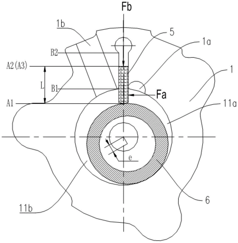
[0003] Affected by the first differential pressure, the sliding vane will deform. In order to control the deformation of the sliding vane within a reasonable range, it is necessary to ensure a certain width of the sliding vane. For example, the width of the sliding vane generally needs to be greater than 3mm, but When the width of the sliding vane is thicker, the second differential pressure force will increase accordingly, thereby indirectly increasing the contact force between the inner end of the sliding vane and the piston, thereby increasing the power of the compressor and affecting the energy efficiency of the rotary compressor. And when the protruding length of the sliding vane is long and the total length of the sliding vane is short, the protruding rate of the sliding vane will be large, which will affect the reliability of the compressor and hinder the flatness of the rotary compressor. development

Method used


Image

  • Compression mechanism for rotary compressor and rotary compressor having the same
  • Compression mechanism for rotary compressor and rotary compressor having the same
  • Compression mechanism for rotary compressor and rotary compressor having the same

Examples


Embodiment Construction

[0027] Embodiments of the present invention are described in detail below, examples of which are shown in the drawings, wherein the same or similar reference numerals designate the same or similar elements or elements having the same or similar functions throughout. The embodiments described below by referring to the figures are exemplary and are intended to explain the present invention and should not be construed as limiting the present invention.

[0028] The following disclosure provides many different embodiments or examples for implementing different structures of the present invention. To simplify the disclosure of the present invention, components and arrangements of specific examples are described below. Of course, they are only examples and are not intended to limit the invention. Furthermore, the present invention may repeat reference numerals and / or letters in different instances. This repetition is for the purpose of simplicity and clarity and does not in itself...


PUM


Abstract

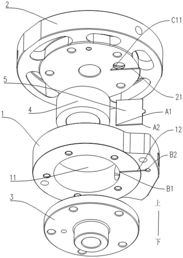
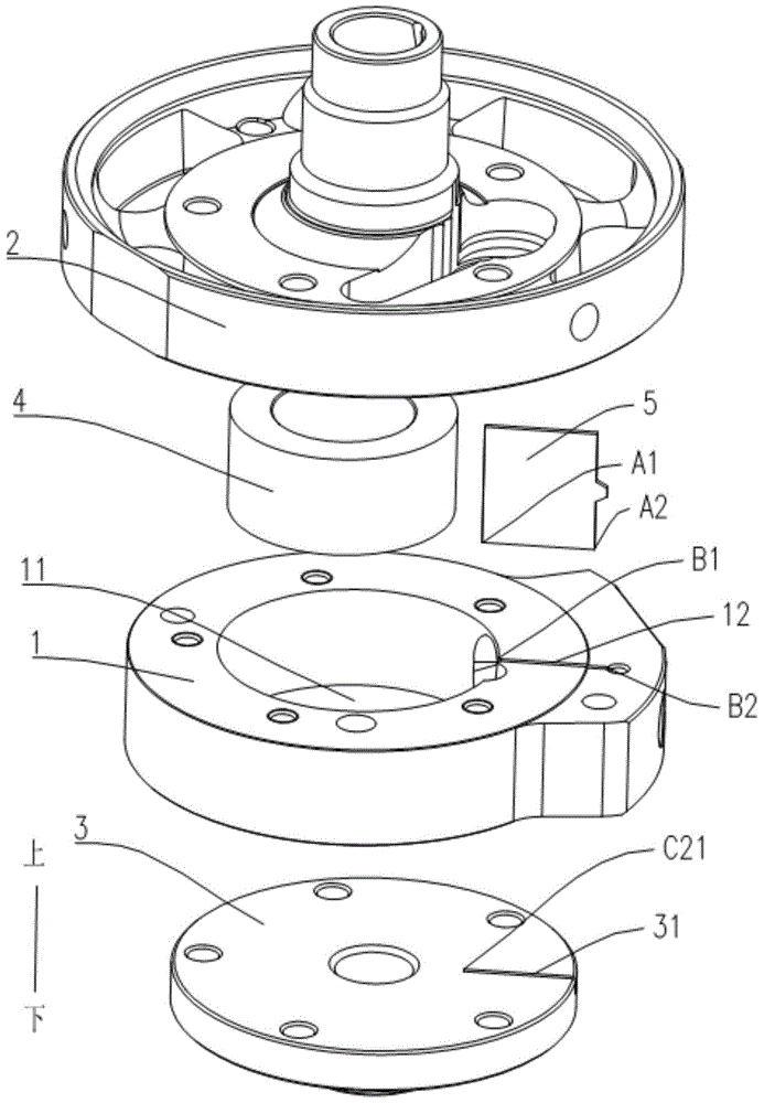
The invention discloses a compression mechanism for a rotary compressor and the rotary compressor with the same. The compression mechanism comprises a cylinder, two bearing pieces, a crank shaft, a piston and a slip sheet, wherein the cylinder is provided with a first slip sheet groove which extends along the radial direction and is communicated with a compression cavity, at least one bearing is provided with a second slip sheet groove which is open towards the cylinder, and the second slip sheet groove corresponds to the first slip sheet groove; a slip sheet groove is formed by the second slip sheet groove and the first slip sheet groove, and the slip sheet is movably arranged in the slip sheet groove. According to the compression mechanism for the rotary compressor, at least one bearing is provided with the second slip sheet groove, so that the problem of bending deformation of the slip sheet is improved, the width of the slip sheet is decreased, and the protrusion rate of the slip sheet is increased; the length of the slip sheet is decreased, the eccentricity of the crank shaft is increased, and the integral energy efficiency of the rotary compressor is improved, and a flat design of the rotary compressor is possibly realized.

Description

technical field [0001] The invention relates to the field of compressor equipment, in particular to a compression mechanism for a rotary compressor and a rotary compressor with the same. Background technique [0002] In the design of the rotary compressor, due to the different pressures of the refrigerant at different parts of the compression mechanism, the differential pressure force on the sliding vane mainly includes the first differential pressure force and the second differential pressure force, where the first differential pressure force is The pressure differential force on the part of the sliding vane protruding into the compression chamber, the first differential pressure force is mainly determined by the protruding length of the sliding vane, the height of the sliding vane, and the pressure of the suction chamber and the exhaust chamber, of which the first The second differential pressure force is the pressure differential force borne by the inner end of the slide ...

Claims


Application Information

Patent Timeline
Patent Type & Authority Patents(China)
IPC IPC(8): F04C18/356F04C29/00
Inventor 达拉郭宏虞阳波
Owner GUANGDONG MEIZHI COMPRESSOR
Learn More