
Auxiliary Pit Type Buffer Structure in Railway Tunnel

A buffer structure and tunnel technology, applied in tunnels, mining equipment, earth-moving drilling, etc., can solve the problems such as the unsuitable use of long shafts in tunnels, the high cost of buffer structures, and the increased efficiency of micro-pressure wave mitigation. Micro-pressure wave effect, the effect of alleviating the micro-pressure wave effect at the opening, and maximizing economic benefits

Active Publication Date: 2017-06-20
CHINA RAILWAY SIYUAN SURVEY & DESIGN GRP
View PDF5 Cites 0 Cited by
  • Summary
  • Abstract
  • Description
  • Claims
  • Application Information

AI Technical Summary

Problems solved by technology

[0005] 1) The current buffer structure in the tunnel needs to extend to the side or above, which is difficult to apply to some terrain environments. For example, it is not suitable to use a long shaft for a tunnel with a high mountain
[0006] 2) For long tunnels, especially long tunnels with concrete sleeper slab track beds, after the number of cross passages increases to a certain extent, the increase in micro-pressure wave mitigation efficiency is not obvious relative to the increased construction cost
[0007] 3) The cost of the existing buffer structure in the tunnel is high, and additional excavation and construction work is required. The implementation of the project is difficult and not economical enough
[0008] 4) The maintenance cost is high, and the maintenance and repair cost is high when there is a blockage or the buffer structure is damaged
[0009] 5) It is not easy to transform the existing tunnel, and the transformation cost is high

Method used


Image

  • Auxiliary Pit Type Buffer Structure in Railway Tunnel
  • Auxiliary Pit Type Buffer Structure in Railway Tunnel
  • Auxiliary Pit Type Buffer Structure in Railway Tunnel

Examples


Embodiment Construction

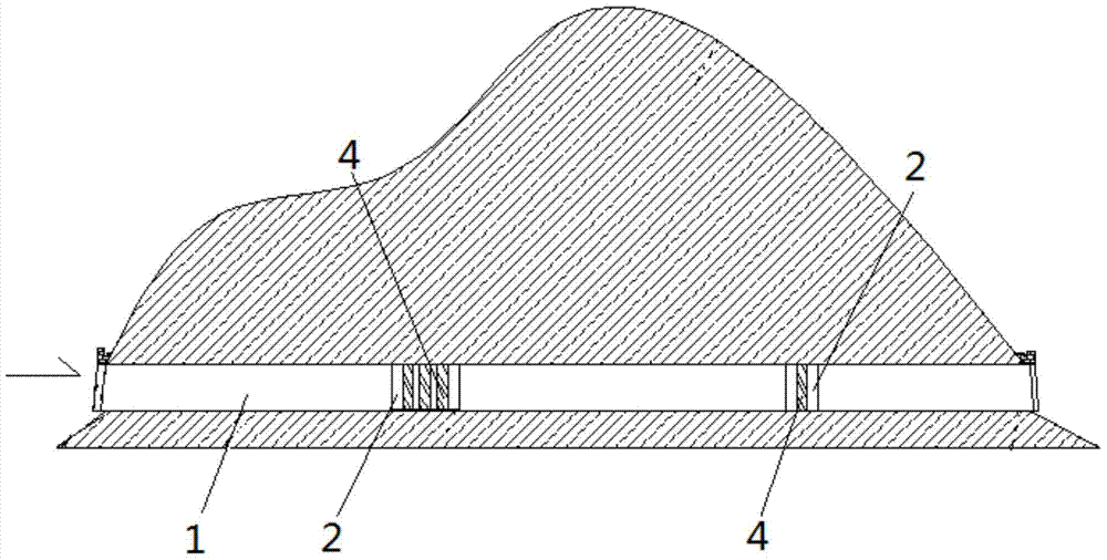
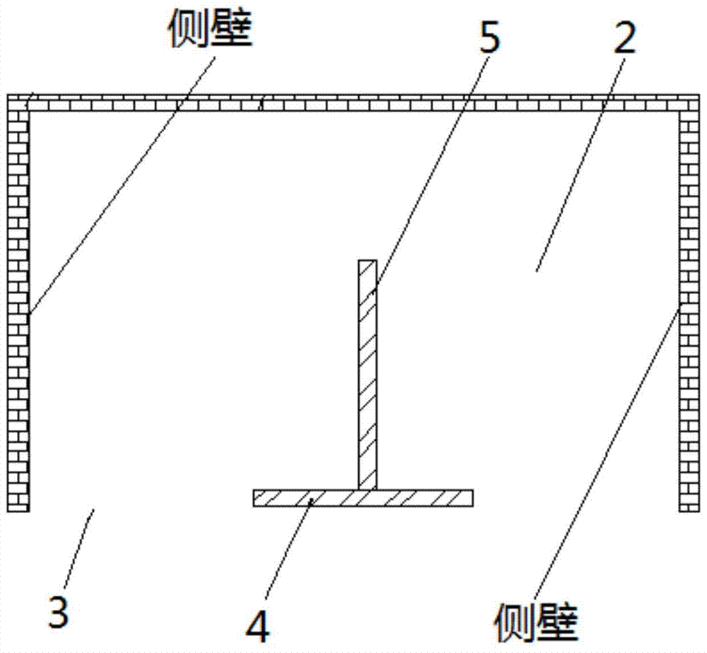
[0028] Such as figure 1 As shown, a plurality of auxiliary pit chambers 2 are arranged on both sides of the tunnel 1, and the plurality of auxiliary pit chambers 2 are arranged at intervals along the axial direction of the tunnel 1, as shown in image 3 with Figure 5 As shown, the auxiliary pit chamber 2 communicates with the tunnel 1 through the opening surface 3 .

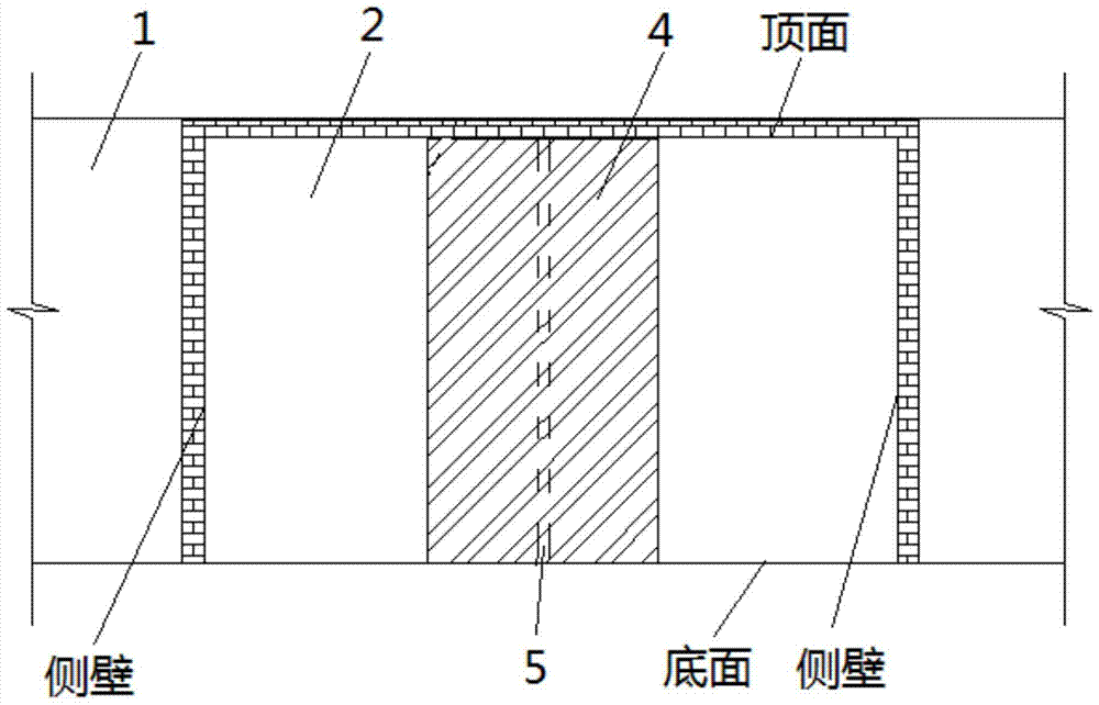
[0029] Such as figure 2 with image 3 As shown, some auxiliary pit chambers 2 in the tunnel 1 are provided with a first baffle plate 4 parallel to the opening surface 3, and both ends of the first baffle plate 4 are fixed to the top and bottom surfaces of the auxiliary pit chamber 2. connected, and the area of ​​the first baffle plate 4 at the same auxiliary pit chamber 2 is smaller than the area of ​​the opening surface 3 of the auxiliary pit chamber 2; and a second baffle plate 5, one end of the second baffle plate 5 is connected to the first baffle plate A baffle plate 4 is connected, and the other end e...


PUM


Abstract

The invention discloses an auxiliary pit type buffering structure in a railway tunnel. The auxiliary pit type buffering structure comprises a plurality of auxiliary pit chambers and second retaining plates; the auxiliary pit chambers are positioned on two sides of the tunnel, are arranged along the axial direction of the tunnel at intervals and are communicated with the tunnel through open surfaces, at least one first retaining plate parallel to the corresponding open surface is arranged at each auxiliary pit chamber, two ends of each retaining plate are fixedly connected with the top surface and the bottom surface of the corresponding auxiliary pit chamber respectively, and the sum of the area of the first retaining plates in the same auxiliary pit chamber is smaller than the area of the open surface of the auxiliary pit chamber; one end of each second retaining plate is connected with the corresponding first retaining plate, and the other end of each second retaining plate extends into the corresponding auxiliary pit chamber. The auxiliary pit type buffering structure has the advantages that the retaining plates are arranged in the auxiliary pit chambers, a compression wave is dispersed, and the pressure peak of a micro compression wave is decreased, so that the micro compression wave effect of a tunnel entrance is remarkably relieved, the tunnel can be renovated at a low cost, the micro compression wave effect of the operational tunnel entrance is relieved, and the buffering structure has remarkable economic benefit and high practicability; the buffering structure is applicable to high speed railways, interurban railways and city field railway tunnels.

Description

technical field [0001] The invention relates to a railway tunnel, in particular to an in-cavity buffer structure for high-speed railways, intercity railways and urban railway tunnels. Background technique [0002] When a high-speed train passes through a tunnel, a series of aerodynamic effects will be induced in the tunnel, among which the most important ones are the transient pressure in the tunnel and the micro-pressure wave at the exit of the tunnel. Among them, the micro-pressure wave will produce obvious blasting sound at the tunnel exit, affect the acoustic environment around the tunnel exit, and make nearby light structures (such as house doors and windows) vibrate sharply. This phenomenon was first discovered in 1975 when Japan conducted a trial run between Okayama and Hakata on the Sanyo Shinkansen, and it was later called the micro-pressure wave phenomenon at the entrance of the cave. Because the micro-pressure wave phenomenon is very harmful to the environment ar...

Claims


Application Information

Patent Timeline
Patent Type & Authority Patents(China)
IPC IPC(8): E21D9/14
CPCE21D9/14
Inventor 赵文成徐向东肖明清
Owner CHINA RAILWAY SIYUAN SURVEY & DESIGN GRP
Learn More