
Single-crank vertical transverse planing cutting machine

A single-crank, planing machine technology, which is applied in the manufacture of flat surface processing machines, wood processing appliances, manufacturing tools, etc., can solve the problems of low planing efficiency, high machine cost, complicated installation, etc. The effect of cutting thickness range, reducing production cost and simplifying the installation process

Active Publication Date: 2015-03-25
青岛豪中豪木工机械有限责任公司
View PDF9 Cites 7 Cited by
  • Summary
  • Abstract
  • Description
  • Claims
  • Application Information

AI Technical Summary

Problems solved by technology

This technology has the following disadvantages at present: one, the structure is huge, the quality is heavy, but the scope of application is limited: it is only suitable for planing timber with a length of more than 3 meters, and the planing thickness is below 3 mm. For short timber, this structure is Second, the installation is complicated: the gap adjustment of the large and small gears is inconvenient; Third, the machining accuracy is high: the rotation phase of the two cranks needs to be synchronized; Fourth, the geometric accuracy is difficult to adjust: the three slide rails Flatness and parallelism are difficult to adjust; 5. High machine cost: the structure of the machine determines the level of production cost, the power requirement of the machine is strong enough, and the cost performance is not high; Low; 7. The mechanical brake device cannot stop the machine at any position during the planing process, and the starting speed of the main vehicle needs to start from zero, and the planing efficiency is low

Method used


Image

  • Single-crank vertical transverse planing cutting machine
  • Single-crank vertical transverse planing cutting machine
  • Single-crank vertical transverse planing cutting machine

Examples


Embodiment Construction

[0028] The present invention will be described in further detail below in conjunction with the accompanying drawings: the present embodiment is implemented on the premise of the technical solution of the present invention, and detailed implementation is provided, but the protection scope of the present invention is not limited to the following embodiments.

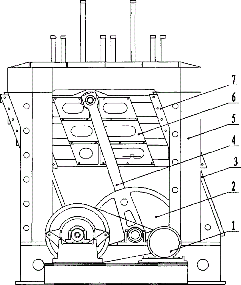
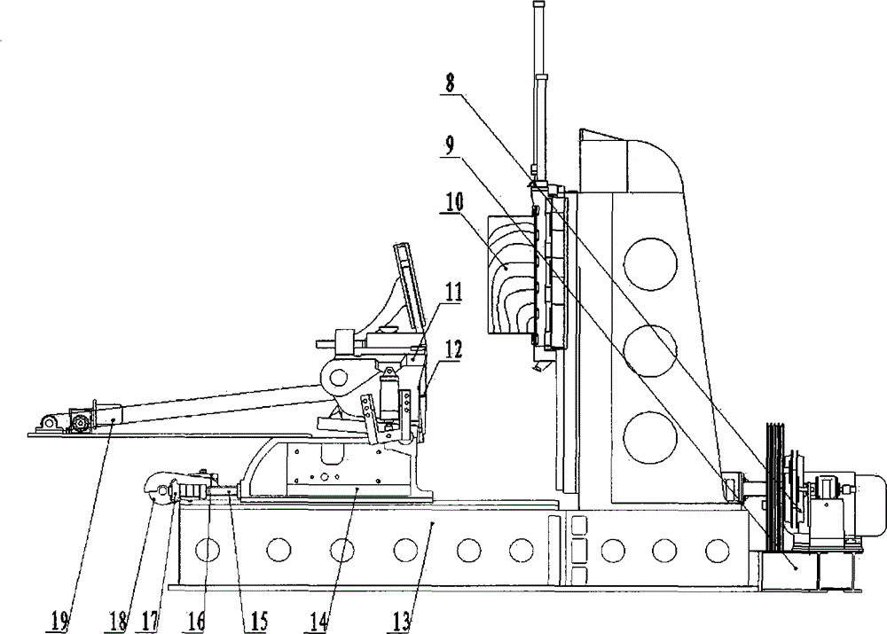
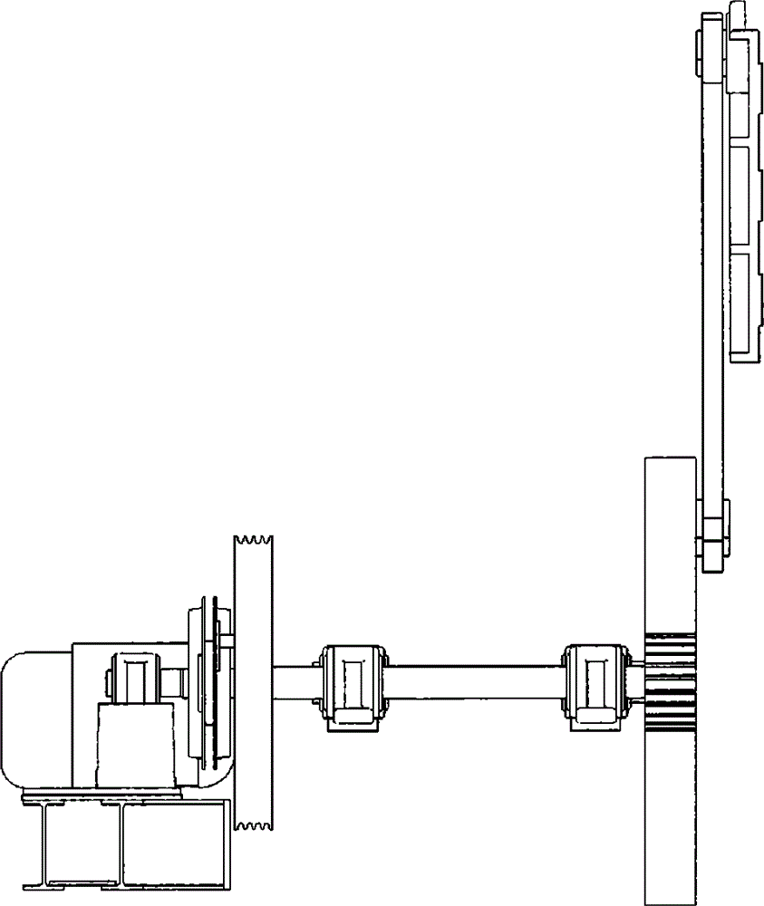
[0029] Such as Figure 1-2 As shown, a single-crank vertical horizontal planer provided in this embodiment includes: a main motor 1, a large gear 2, a slide rail 3, a single-crank mechanism 4, a column frame 5, a wooden platform 6, Lifting slide 7, brake clutch 8, motor support 9, knife holder mechanism 11, planer 12, body 13, feeding slide 14, ball screw 15, servo motor 16, bevel gear 17, Martin transmission 18, transmission sheet device 19.

[0030] The single-crank vertical transverse planer adopts a single crank as the main transmission mode, and adopts a pneumatic brake clutch device as a braking system, and the foot...


PUM


Abstract

The invention relates to a single-crank vertical transverse planing cutting machine, which comprises a main motor, a gear wheel, a sliding rail, a single crank mechanism, a column framework, a wooden square table, a lifting sliding base, a brake clutch, a motor support, a cutter rest mechanism, a planing cutter, a machine body, a material-conveying sliding base, a ball screw, a servo motor, a bevel gear, a Martin transmission and a sheet-conveying mechanism, wherein the single-crank vertical transverse planing cutting machine adopts a single crank as a main transmission way, adopts the pneumatic brake clutch device, and uses a feeding mechanism for automatically feeding a servo system. Seen from the technical scheme provided by the invention, the single-crank vertical transverse planing cutting machine has the benefits as follows: on the premise of meeting a planing condition, a base of the machine body adopts a split structure, the column framework is firm and stable, main transmission adopts the single crank mechanism, and feeding is subjected to servo control, so that the production cost of equipment is reduced, the mounting process is simplified, transportation is facilitated and the range of the planing thickness is widened; the most important aim of the single-crank vertical transverse planing cutting machine is to meet user needs and make special customization easy.

Description

technical field [0001] The invention relates to a single-crank vertical transverse planer, which belongs to the technical field of woodworking machinery manufacturing. Background technique [0002] At present, the structure type of vertical horizontal slicer is mostly double-crank vertical horizontal slicer. The system is also mostly mechanical. This technology has the following disadvantages at present: one, the structure is huge, the quality is heavy, but the scope of application is limited: it is only suitable for planing timber with a length of more than 3 meters, and the planing thickness is below 3 mm. For short timber, this structure is Second, the installation is complicated: the gap adjustment of the large and small gears is inconvenient; Third, the machining accuracy is high: the rotation phase of the two cranks needs to be synchronized; Fourth, the geometric accuracy is difficult to adjust: the three slide rails Flatness and parallelism are difficult to adjust; ...

Claims


Application Information

Patent Timeline
IPC IPC(8): B27C1/00B27C1/14
CPCB27C1/00B27C1/14
Inventor 刘维汉刘风杰曲明春
Owner 青岛豪中豪木工机械有限责任公司
Learn More