A material conveying mechanism for ferrule workpiece processing

A technology for conveying mechanisms and workpieces, which is applied to metal processing equipment, manufacturing tools, and parts of grinding machine tools. It can solve the problems of large space occupation, inconvenience, and damage to ferrules, and achieve the effect of small space occupation.

Active Publication Date: 2017-01-25
经纬光学科技(苏州)有限公司
View PDF6 Cites 0 Cited by
  • Summary
  • Abstract
  • Description
  • Claims
  • Application Information

AI Technical Summary

Problems solved by technology

[0004] When the existing ferrules are processed on the grinding machine, they need to be conveyed. The existing conveying device generally uses a vibrating feeding plate for feeding. Vibrating feeding is generally used for the initial processing of ferrules. Yes, because the vibrating feeding is easy to damage the ferrule, so it is generally not used in finishing, so the only way is to lengthen the conveyor belt and make the roughing and finishing on the same production line to make the roughing finished. The products are directly sent to the finishing place through the conveyor belt, which makes the production line longer and takes up a lot of space, which is very inconvenient

Method used


Image

  • A material conveying mechanism for ferrule workpiece processing
  • A material conveying mechanism for ferrule workpiece processing
  • A material conveying mechanism for ferrule workpiece processing

Examples


Embodiment Construction

[0020] The following describes the present invention in detail with reference to the accompanying drawings and specific preferred embodiments, so that the advantages and features of the present invention can be more easily understood by those skilled in the art. These embodiments are for illustrative purposes only, and are not intended to improve the present invention. The scope is limited.

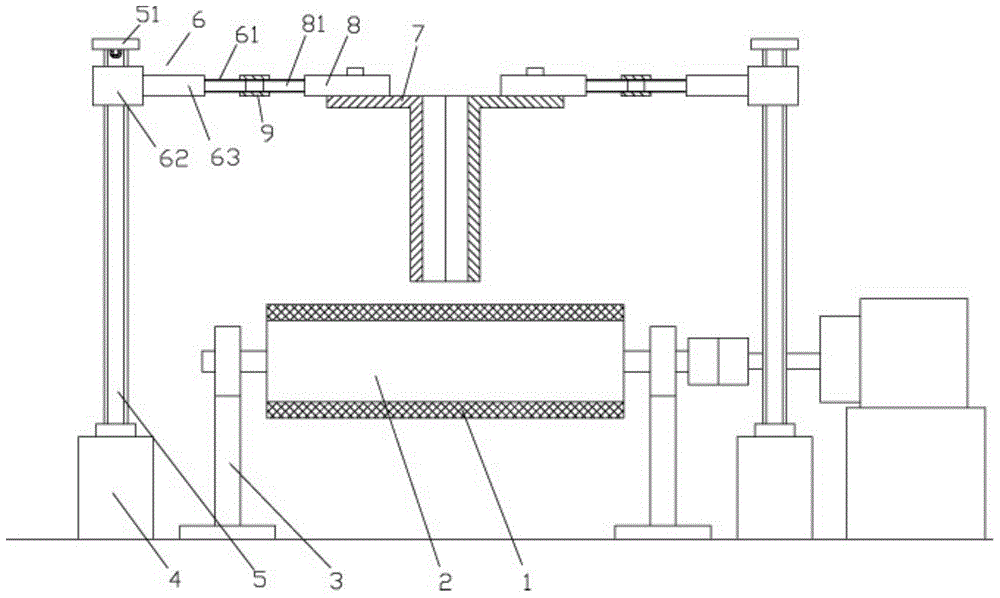
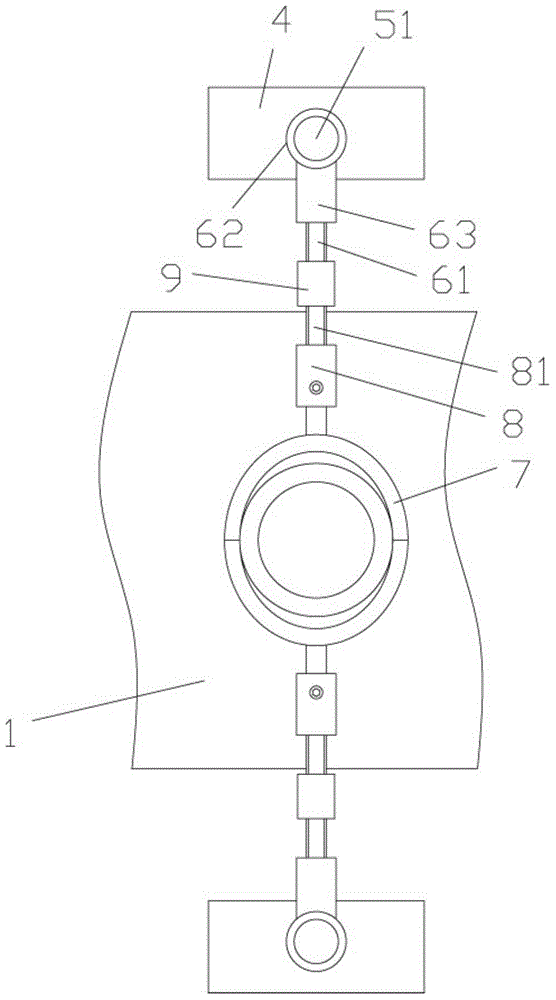
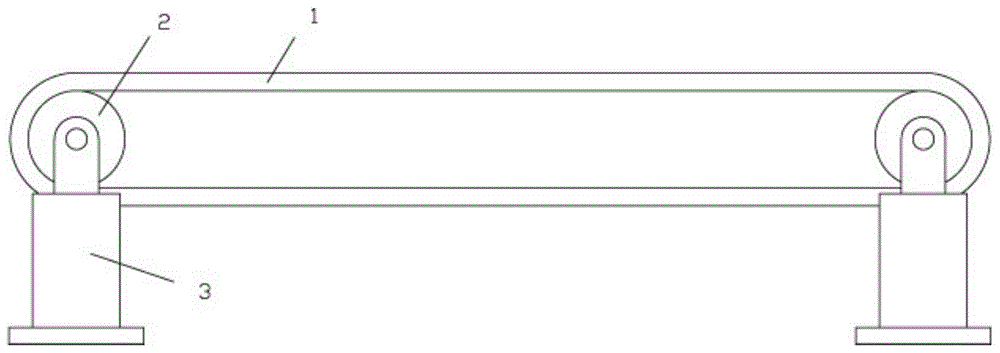
[0021] Example, see as Figure 1 to Figure 3 As shown, a ferrule workpiece processing and unloading conveying mechanism includes a conveyor belt 1. The conveyor belt 1 is tensioned between two rotating rollers 2, and the two rotating rollers 2 are fixed with support seats 3 at both ends, one of which One end of the rotating roller 2 extends out of the support base 3 and is connected to the output shaft of the drive motor through a coupling; connecting blocks 4 are fixed on both sides of the conveyor belt 1, and the upper end of the connecting block 4 is hinged with a rotating screw 5, and th...


PUM


Abstract

The invention discloses a discharging conveying mechanism used in the machining of ferrule workpieces. The discharging conveying mechanism comprises a conveying belt tensioned between two rotating rollers. Two ends of the rotating rollers are fixedly provided with supporting seats. One end of one of the rotating rollers extends out of the corresponding supporting seat to be connected with an output shaft of a drive motor through a coupler. Connecting blocks are fixed on two sides of the conveying belt. The upper ends of the connecting blocks are hinged to rotating screws. Lifting blocks are in screw connection with the upper ends of the rotating screws and provided with connecting screws. Two circular clamping blocks which are fixed on main adjusting blocks are arranged right over the conveying belt and combined to form an oval circular column. Auxiliary connecting screws are arranged on the main adjusting blocks. Two ends of each auxiliary connecting screw and two ends of each connecting screws are in screw connection into two ends of an adjusting sleeve. The discharging conveying mechanism does not need to be placed in a production line where rough machining is performed, functions in automatic discharging and is small in size and adjustable, thus meeting requirements of the ferrules of different sizes.

Description

[0001] Technical field: [0002] The invention relates to the technical field of machining, and more specifically to a feeding and conveying mechanism for processing a ferrule workpiece. [0003] Background technique: [0004] Existing ferrules need to be transported when they are processed on a grinder. The existing transport device generally uses a vibrating feeding tray for feeding, and vibrating feeding is generally used for the initial processing of ferrules Yes, because vibration feeding is easy to damage the ferrule, it is generally not used during finishing. In this way, the conveyor belt can be lengthened and the roughing and finishing are on the same production line so that the roughing is completed. The product is directly sent to the finishing place through the conveyor belt, which makes the production line longer, takes up a large space, and is very inconvenient. [0005] Summary of the invention: [0006] The purpose of the present invention is to overcome the shortcoming...

Claims


Application Information

Patent Timeline
Patent Type & Authority Patents(China)
IPC IPC(8): B24B41/00
CPCB24B41/005
Inventor 杨建华
Owner 经纬光学科技(苏州)有限公司
Why Eureka
Try Eureka