
Emulsification method and emulsification device for lead-acid battery colloidal electrolyte thickener

A colloidal electrolyte, lead-acid battery technology, applied in chemical instruments and methods, mixers with rotary stirring devices, dissolution and other directions, can solve problems such as agglomeration and deposition, and achieve the promotion of dissolution and mixing, high efficiency, and prevention of deposition. Effect

Active Publication Date: 2016-07-06
CHAOWEI POWER CO LTD
View PDF4 Cites 0 Cited by
  • Summary
  • Abstract
  • Description
  • Claims
  • Application Information

AI Technical Summary

Problems solved by technology

[0004] The invention provides an emulsification method and an emulsification device for a colloidal electrolyte thickener of a lead-acid battery capable of preventing deposition and agglomeration, which solves the problem of easy agglomeration and deposition in the emulsification process of a colloidal electrolyte thickener for a lead-acid battery question

Method used


Image

  • Emulsification method and emulsification device for lead-acid battery colloidal electrolyte thickener
  • Emulsification method and emulsification device for lead-acid battery colloidal electrolyte thickener
  • Emulsification method and emulsification device for lead-acid battery colloidal electrolyte thickener

Examples


Embodiment 1

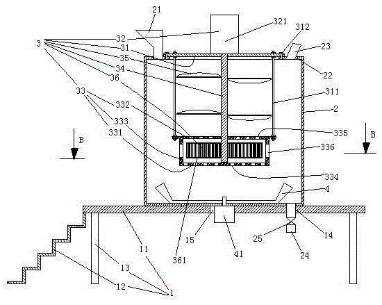
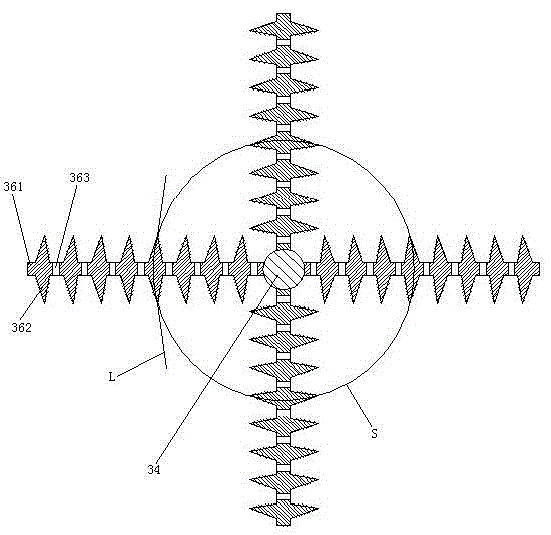
[0041] Embodiment one, see figure 1 , an emulsification device, including a support table 1, a container 2 and a stirrer 3.

[0042] The support platform 1 includes a panel 11 and a staircase 12 . The upper end of the stairs 12 is connected with the panel 11. The panel 11 is provided with supporting feet 13 , discharge holes 14 and motor through holes 15 .

[0043] A feed hopper 21 and an observation port 22 are provided on the top wall of the container 2 . The observation port 22 is fixedly connected with an observation tube 23 . The bottom wall of the container 2 is provided with a discharge pipe 24 . The discharge pipe 24 extends to the lower space of the panel 11 through the discharge hole 14 . The discharge pipe 24 is provided with a discharge valve 25 . The discharge valve 25 is an electric valve. The container 2 rests on the panel 11 . A wall scraping paddle 4 is also provided in the container 2 . The wall-scraping paddle 4 is attached to the inner surface of t...

Embodiment 2

[0051] Embodiment two, the difference with embodiment one is:

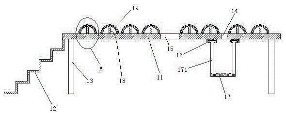
[0052] see image 3 , The upper surface of the panel 11 is provided with several supporting protrusions 18 . The height of the supporting protrusion 18 is less than 2 centimeters. The upper end of the support protrusion 18 is connected with a suction cup 19 . The suction cup 19 is turned down to the opening facing downwards and covered on the support protrusion 18 . A bracket 17 is provided below the panel 11 . A slide rail 16 is provided on the lower surface of the panel 11 . There are two slide rails 16. The slide rail 16 extends to the edge of the panel 11 . The discharge hole 14 is located between two slide rails 16 . The bracket 17 is provided with two hanging arms 171 . The lower ends of the two hanging arms 171 are connected to the two ends of the bracket 17 . The upper ends of the two hanging arms 171 are slidably suspended on the two slide rails 16 in a one-to-one correspondence.

[0053] see ...

Embodiment 3

[0056] Embodiment three, the difference with embodiment two is:

[0057] see Image 6 , The agitator also includes a lifting mechanism 37. The quantity of lifting mechanism 37 is equal to the quantity of stirring blade 35. The lifting mechanism 37 includes a chute 371 , a slider 372 , a screw rod 373 and a lifting motor 374 . The slide slot 371 is disposed on the rotating shaft 34 . The slide slot 34 extends axially along the rotating shaft 34 . The sliding block 372 is slidably connected in the slide groove 371 . The stirring blades 35 and the sliders 372 are connected together in a one-to-one correspondence. The screw rod 373 extends in the vertical direction. The threaded rod 372 is screwed to the slider 372 and passes through the slider 372 . The power output shafts of the screw mandrel 373 and the lifting motor 374 are coaxial and connected together. The lift motor 374 is connected to the upper end of the rotating shaft 34 .

[0058] The shaft driving mechanism 3...


PUM


Abstract

The invention relates to the field of production of storage batteries, and particularly relates to a method for emulsifying a lead-acid storage battery gel electrolyte thickener and an emulsifying device, which can be used for solving the problems that the lead-acid storage battery gel electrolyte thickener easily agglomerates and precipitates during emulsification. The method for emulsifying a lead-acid storage battery gel electrolyte thickener comprises the following steps: heating in a container, mixing by using a mixer, scraping the bottom wall of the containing by using a wall scraping blade and emulsifying in a manner of cutting by using a static cavity which sleeves a rotating shaft of the mixer in the container and cutting blades which are positioned in the static cavity and connected with the rotating shaft of the mixer. An emulsifying device comprises the container, the mixer, the wall scraping blade and the static cavity, wherein the mixer comprises the rotating shaft and a plurality of mixing blades positioned in the container, the wall scraping blade is attached to the inner surface of the bottom wall of the container, the rotating shaft extends along the up-and-down direction, the static cavity sleeves the rotating shaft which is connected with the cutting blades, the cutting blades are positioned in the static cavity, a communication hole is formed in the wall of the static cavity, and the mixing blades are positioned outside the static cavity.

Description

technical field [0001] The invention relates to the field of storage battery production, in particular to an emulsification method and an emulsification device for a colloidal electrolyte thickener of a lead-acid storage battery. Background technique [0002] In the process of preparing colloidal electrolyte for lead-acid batteries, the thickener needs to be dissolved and emulsified in advance. The existing thickener is dissolved and emulsified by electric heating and synchronous stirring. Emulsification is done in a stirred tank. An existing stirred tank is disclosed in a patent document with the Chinese patent application number 2013102815248, published on October 2, 2014, and titled "a stirred tank with double stirrers". The required stirred tank includes a container and an agitator arranged in the container, the container is provided with a discharge pipe, the inlet end of the discharge pipe is located at the middle and lower part of the container, and the agitator incl...

Claims


Application Information

Patent Timeline
Patent Type & Authority Patents(China)
IPC IPC(8): B01F1/00B01F7/16B01F15/06
Inventor 张森赵文超
Owner CHAOWEI POWER CO LTD
Learn More