Chemical laboratory waste gas treating method and chemical laboratory waste gas treating device

A chemical laboratory and waste gas treatment technology, applied in chemical instruments and methods, separation methods, dispersed particle separation, etc., can solve problems such as failure to meet emission standards, damage to the life and health of employees and local people, and failure to meet the requirements of national development. , to achieve the effect of high absorption capacity, high solubility, and zero excessive discharge

Inactive Publication Date: 2015-03-25
芒市海华开发有限公司
View PDF4 Cites 12 Cited by
  • Summary
  • Abstract
  • Description
  • Claims
  • Application Information

AI Technical Summary

Problems solved by technology

[0003] In my country, fuel combustion and industrial waste gas emissions are the main sources of air pollution. Up to now, these pollutions have caused great harm. In many places, factories and laboratories, waste gas is directly discharged into the atmosphere without any treatment. , some enterprises or factories, although they adopt certain treatment methods for waste gas, do not meet the emission standards required by the state. Even in laboratories in some developed areas, the waste gas emitted is often only treated in a simple ventilation cabinet. In remote areas, some large-scale chemical plants, smelters, and laboratories have not done any treatment of exhaust gas at all, which has brought great damage to the lives and health of employees and local people, and the consequences are extremely serious
[0004] To sum up, the current common exhaust gas treatment methods do not meet the requirements of national development and cannot meet the needs of people's health. Therefore, it is particularly important to develop a safe, hygienic and clean exhaust gas treatment process

Method used


Image

  • Chemical laboratory waste gas treating method and chemical laboratory waste gas treating device

Examples


Embodiment Construction

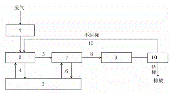
[0015] Such as figure 1 Shown: The exhaust gas produced in the chemical laboratory passes through the fume hood 1 with a sponge inside, and the dust contained in the exhaust gas is removed through the adsorption of the sponge; the gas after dust removal by the sponge is introduced into the first-level lye countercurrent spray tower 2 In the process, through the circulation pump 4, the NaOH solution with a mass concentration of 10% in the lye storage tank 3 is sprayed from the top of the primary lye countercurrent spray tower 2 (the amount of NaOH added in stages to ensure a mass concentration of 10%), to remove large amounts of Part of the acidic gas and soluble alkaline neutral gas; the residual gas is introduced into the secondary lye countercurrent spray tower 7 through the blower fan 5, and the residual gas is removed by the same treatment method as the primary lye countercurrent spray tower 2. more soluble gas; the remaining gas is introduced into the high-efficiency acti...


PUM


Abstract

The invention relates to a chemical laboratory waste gas treating method and a chemical laboratory waste gas treating device. The method comprises the steps of removing dust of waste gas generated in a chemical laboratory through sponge, guiding the waste gas into a primary alkaline countercurrent tower through a fan via a ventilation cabinet, removing a great amount of acid gas, soluble alkaline and neutral waste gas, further absorbing the waste gas which cannot be absorbed in the primary alkaline countercurrent tower by virtue of a secondary alkaline countercurrent tower, exhausting the surplus gas into a high-efficiency activated carbon adsorption tower through a centrifugal fan, and adsorbing the surplus waste gas which is difficult to treat by virtue of the high-efficiency activated carbon; detecting the remaining gas after being adsorbed by activated carbon, discharging the gas if the gas is qualified by detection, pumping the gas to the primary alkaline countercurrent absorption tower by adopting a circulating air pump if the gas is unqualified by the detection so as to enable the gas to be circularly treated, and discharging the gas until the gas reaches the standard by the detection. By adopting the method and the device, the discharging of the pollution gas without exceeding the standard can be realized.

Description

technical field [0001] The invention relates to a method and equipment applicable to the treatment of various types of chemical laboratory waste gas. Background technique [0002] In the past 30 years, my country's economy has made great achievements, but it has also paid a huge price, including the cost of resources and the environment. With the improvement of people's living standards and the improvement of living standards, the society's environmental pollution More and more attention, therefore, only clean development, environment-friendly development can meet the needs of our country's future. [0003] In my country, fuel combustion and industrial waste gas emissions are the main sources of air pollution. Up to now, these pollutions have caused great harm. In many places, factories and laboratories, waste gas is directly discharged into the atmosphere without any treatment. , some enterprises or factories, although they adopt certain treatment methods for waste gas, do n...

Claims


Application Information

Patent Timeline
IPC IPC(8): B01D53/78B01D53/40B01D46/30
Inventor 陈水奇代毕龙陈铁华许春景
Owner 芒市海华开发有限公司
Why Eureka
Try Eureka