A novel overflow sieve tray column with curved sieve tray

A sieve plate tower and overflow type technology, which is applied in the field of sieve plate tower, can solve the problems of unfavorable gas and liquid full contact, liquid is easy to block the sieve holes, and the gas output is small, so as to achieve enhanced pressure and increased contact volume , the effect of uniform contact

Inactive Publication Date: 2016-01-20
DATANG LUOYANG CO GENERATION POWER
View PDF5 Cites 0 Cited by
  • Summary
  • Abstract
  • Description
  • Claims
  • Application Information

AI Technical Summary

Problems solved by technology

[0003] If the sieve plate of the sieve plate tower is unreasonably designed, it will be in a low-pressure state in the tower. If the sieve hole is too large, the liquid will easily block the sieve hole, which is not conducive to the gas rising from the sieve hole to pass through the liquid layer. If the sieve hole is too small, The gas output is small, which is not conducive to the full contact of gas and liquid

Method used


Image

  • A novel overflow sieve tray column with curved sieve tray
  • A novel overflow sieve tray column with curved sieve tray
  • A novel overflow sieve tray column with curved sieve tray

Examples


Embodiment 1

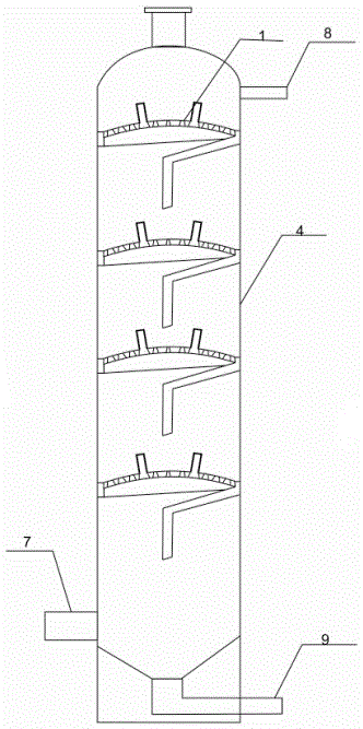
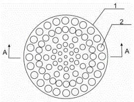
[0026] Install the sieve plate layer by layer in the sieve plate tower. The sieve plate adopts a circular arc panel with a high center and a low surrounding area. There are round holes or oval holes on the sieve plate. Multiple sieve holes are evenly arranged on the sieve plate. On the top, it gradually becomes larger from the middle of the sieve plate to the surroundings. There are also multiple hollow columns on the sieve plate. The multiple hollow columns form a circle on the sieve plate. There is a gap between the columns to prevent the flow of liquid. Flow, there are multiple sieves on the top of the side of the column, the gas contacts the liquid from a horizontal angle, and passes through the gaseous gas to be rectified into the tower, the gas is discharged from the tower through the sieves, and passes through the reboiler and condenser to achieve In the saturated state, the reflux liquid enters the tower through the liquid inlet pipe, contacts and mixes with the gas thr...

Embodiment 2

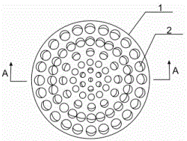
[0028] Install the sieve plate layer by layer in the sieve plate tower. The sieve plate adopts a circular arc panel with a high center and a low surrounding area. There are round holes or oval holes on the sieve plate. Multiple sieve holes are evenly arranged on the sieve plate. On the top, it gradually becomes larger from the middle of the sieve plate to the surroundings. There are also multiple hollow columns on the sieve plate. The multiple hollow columns form a circle on the sieve plate. There is a gap between the columns to prevent the flow of liquid. Flow, there are multiple screen holes on the top of the side of the column, the gas is in contact with the liquid from a horizontal angle, and there is a shielding arc plate on the screen hole, which is an outwardly convex arc surface, covering part of the screen hole , the mouth between the shielding arc plate and the sieve hole is aligned with the center of the sieve plate, and the gaseous gas to be rectified passes through...


PUM


Abstract

The invention discloses an overflow type sieve-plate tower with a novel arc-shaped sieve plate. The overflow type sieve-plate tower comprises a tower body, wherein an air inlet pipe and a return fluid inlet pipe are arranged on the tower body, and a liquid outlet pipe is arranged at the bottom of the tower body; a sieve plate is arranged on the tower body and is an arc-shaped plate which is high in middle and low in edge; the radian of the sieve plate is gradually reduced from the top to the bottom of the tower body; a hollow upright post communicated with the bottom surface of the sieve plate is arranged on the sieve plate; sieve pores are formed in the surface of the sieve plate and the side wall of the upright post; the sizes of the sieve pores in the surface of the sieve plate are gradually increased from the middle to the edge of the sieve plate; a liquid collection tank used for collecting return fluid is arranged at the periphery of the sieve plate; and the fluid is supplied to the sieve plate on the next layer by a pipeline by virtue of the liquid collection tank. By utilizing the arc-shaped structure, gas in liquid in the tower is fully contacted, the service effect of the sieve plate is improved, and the rectification effect of the sieve-plate tower is improved.

Description

technical field [0001] The invention relates to a sieve plate tower, in particular to an overflow type sieve plate tower with a novel curved sieve plate. Background technique [0002] Sieve tray tower is a kind of Zhaban tower, which is equipped with several layers of horizontal trays. There are many small holes on the plates, which are shaped like sieves; and overflow pipes or no overflow pipes are installed. During operation, the liquid enters from the top of the tower, descends plate by plate through the overflow pipe (part of which passes through the sieve), and accumulates a liquid layer on the plate. The gas (or steam) enters from the bottom of the tower, rises through the sieve, passes through the liquid layer, and bubbles out, so that the two phases can fully contact and interact. A form of foam contact gas-liquid mass transfer process that outperforms bubble columns. [0003] If the sieve plate of the sieve plate tower is unreasonably designed, it will be in a low...

Claims


Application Information

Patent Timeline
Patent Type & Authority Patents(China)
IPC IPC(8): B01D3/16
Inventor 王丙欣王军见王红垒
Owner DATANG LUOYANG CO GENERATION POWER
Why Eureka
Try Eureka