A high power density permanent magnet motor rotor structure and a motor using it
A high power density, permanent magnet motor technology, applied in the direction of magnetic circuit shape/style/structure, synchronous motor with stationary armature and rotating magnet, magnetic circuit rotating parts, etc., can solve the problem that the efficiency of the motor cannot be fully improved, The performance of the excitation magnetic steel cannot be fully utilized, and the power density of the motor is limited.
- Summary
- Abstract
- Description
- Claims
- Application Information
AI Technical Summary
Problems solved by technology
Method used
Image

Examples
Embodiment 1
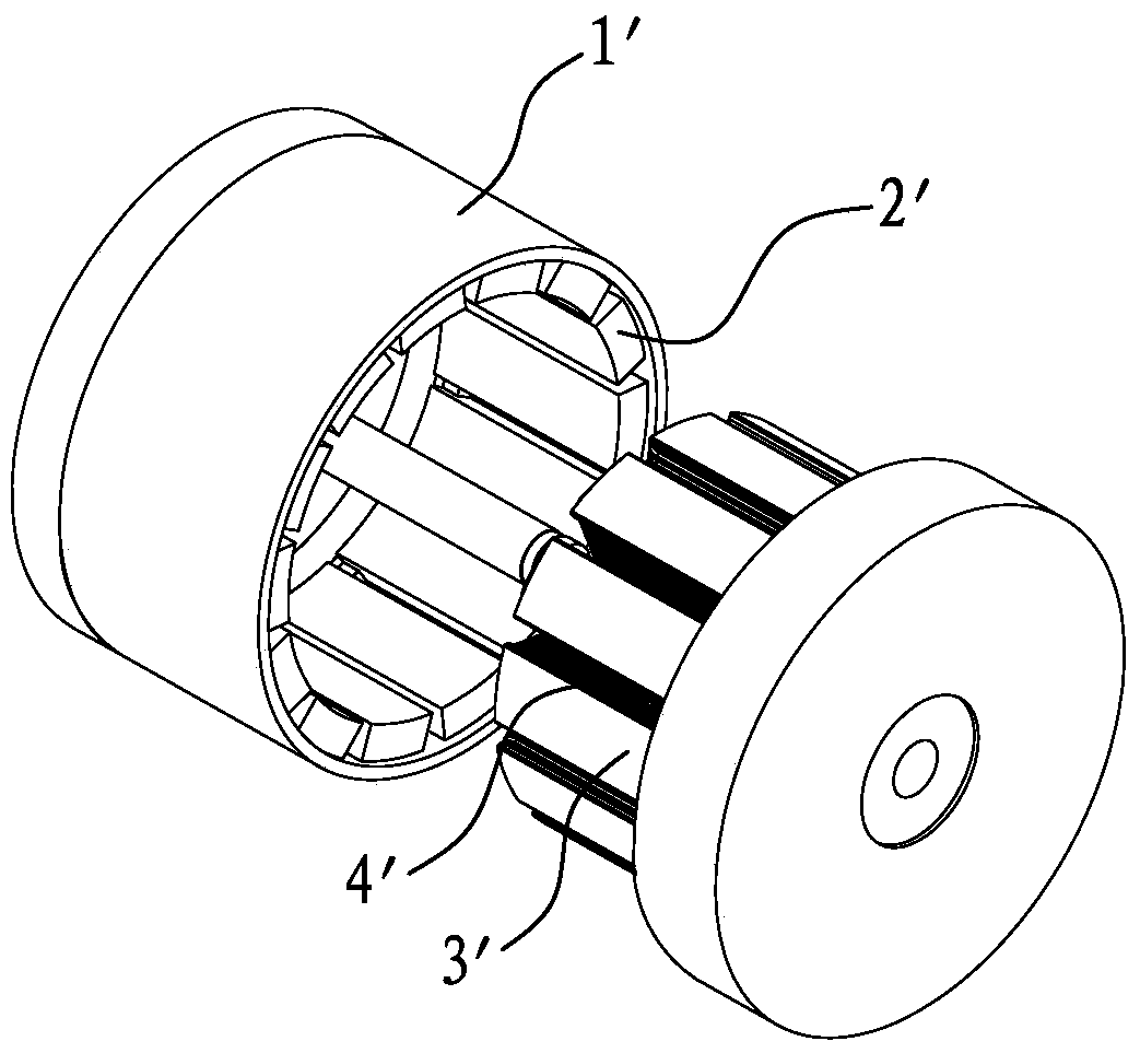
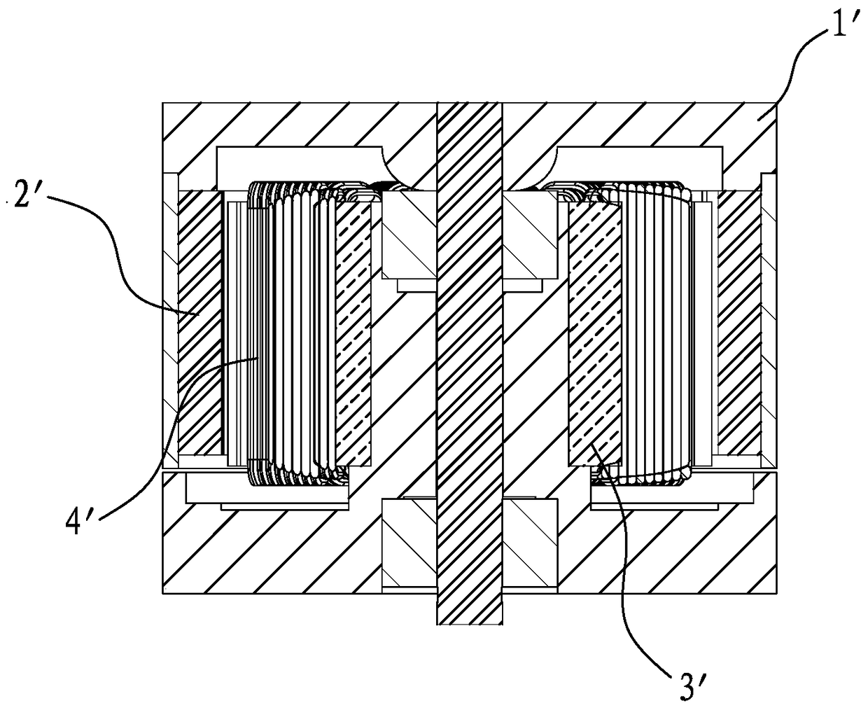
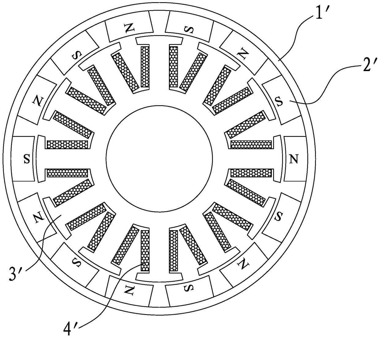
[0035] refer to Figure 5 , 6 As shown, the present invention discloses a high power density motor rotor structure, which includes a rotor casing 1, a rotor excitation magnetic steel 2, and a magnetic wedge 5, wherein:
[0036] The magnetic wedges 3 are made of ferromagnetic materials, which are set as a group, and are respectively arranged in the gaps between the N pole and the S pole of the rotor exciting magnetic steel 2 . In specific implementation, the magnetic wedges 5 can be made of ferromagnetic materials such as electrical steel. In addition, the magnetic wedges 5 are of a split type and formed one by one. After the magnetic wedge 5 is made of a ferromagnetic material such as electrical steel, its mechanical strength is very high, and the size can be precisely controlled. Therefore, after the magnetic wedge 5 made of ferromagnetic material is installed on the rotor, The rotor exciting magnetic steel 2 can also be supported to enhance the mechanical strength of the r...
Embodiment 2
[0042] refer to Figure 10 As shown, it is a schematic structural diagram of the second embodiment of the permanent magnet synchronous motor of the present invention. Compared with the first embodiment, the difference lies in:
[0043] In this embodiment, the magnetic wedge 5 includes a ring 51 and a set of vertical rods 52 arranged on the ring 51. In this embodiment, the vertical rod 52 and the ring 51 are integrally formed. The rod 52 is located in the gap between the N pole and the S pole of the rotor field magnet 2 .
[0044] The integrated design enables better control of assembly precision and more convenient assembly. And better strengthen the mechanical strength of the rotor.
Embodiment 3
[0046] refer to Figure 11 As shown, it is a schematic structural diagram of the third embodiment of the permanent magnet synchronous motor of the present invention. Compared with the first embodiment, the difference lies in:
[0047] In this embodiment, the magnetic wedge 5 is formed into a cylindrical body, and a groove 53 for accommodating the rotor exciting magnetic steel 2 is uniformly provided on the cylindrical wall of the cylindrical body. When in use, the rotor excitation magnetic steel 2 is evenly installed in the slot 53 , and the rods 52 between each slot 53 are located in the gap between the N pole and the S pole of the rotor excitation magnetic steel 2 . The structure of the magnetic wedge 5 not only enhances the thickness of the rotor yoke in the gap between the N pole and the S pole of the rotor excitation magnetic steel 2 of the rotor casing 1, but also strengthens the rotor casing 1 and the rotor excitation magnetic steel 2. The thickness of the contact loca...
PUM
 Abstract
Description
Claims
Application Information
 - R&D
- Intellectual Property
- Life Sciences
- Materials
- Tech Scout
- Unparalleled Data Quality
- Higher Quality Content
- 60% Fewer Hallucinations
Browse by: Latest US Patents, China's latest patents, Technical Efficacy Thesaurus, Application Domain, Technology Topic, Popular Technical Reports.
© 2025 PatSnap. All rights reserved.Legal|Privacy policy|Modern Slavery Act Transparency Statement|Sitemap|About US| Contact US: help@patsnap.com