
Ion source and ion implantation device

A technology of ion source and plasma, which is applied in the field of ion source and ion implantation device, can solve the problems of poor filament relay capability, affecting production capacity, disconnection, etc., and achieve the effect of improving efficiency and increasing production capacity

Active Publication Date: 2015-03-18
SEMICON MFG INT (SHANGHAI) CORP
View PDF3 Cites 5 Cited by
  • Summary
  • Abstract
  • Description
  • Claims
  • Application Information

AI Technical Summary

Problems solved by technology

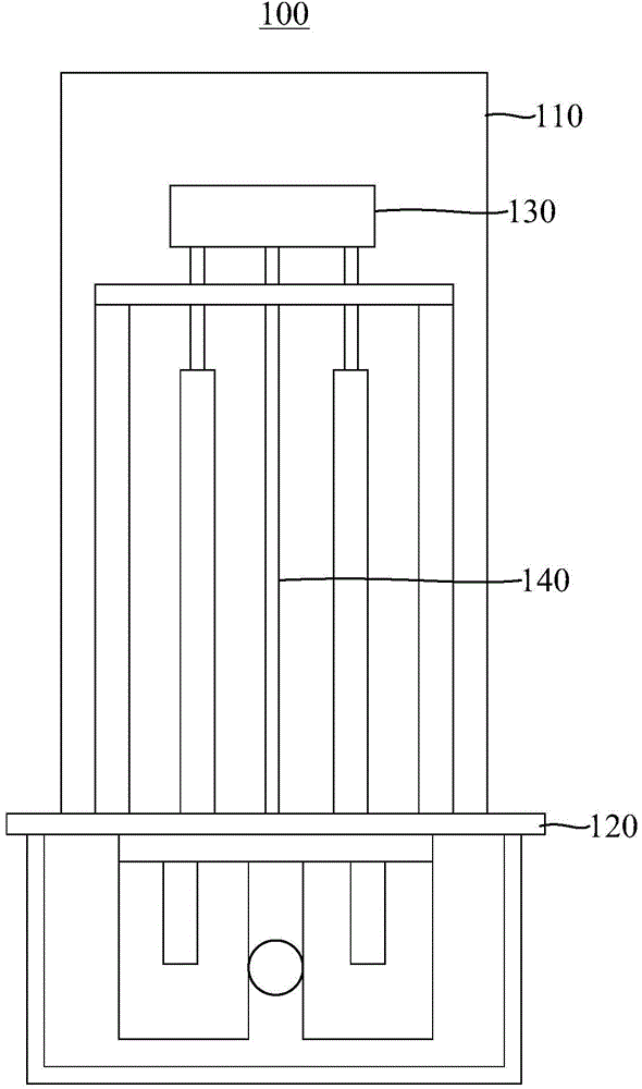
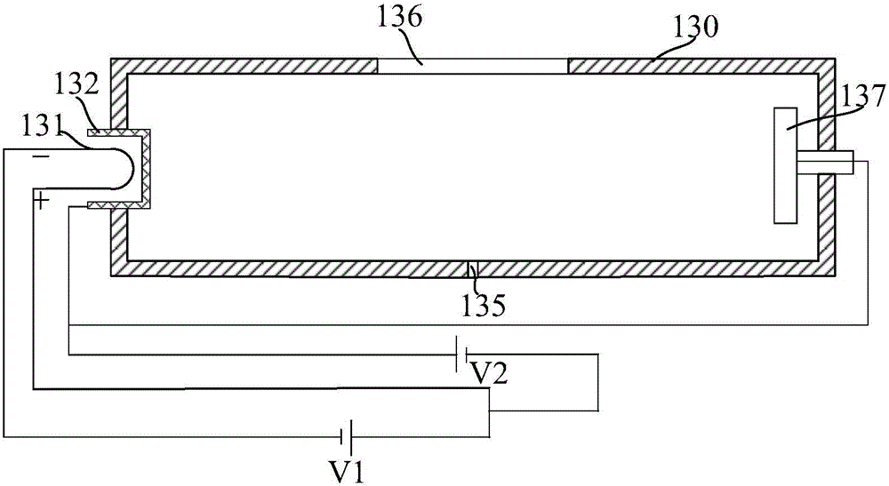
[0007] However, in the prior art, the first cathode 131 is generally a filament, which is easily consumed during the working process, causing the relay capability of the filament to deteriorate, or if the wire is broken, then the ion source must be stopped and the vacuum chamber must be opened. 110 for maintenance, thereby affecting capacity

Method used


Image

  • Ion source and ion implantation device
  • Ion source and ion implantation device
  • Ion source and ion implantation device

Examples


Embodiment Construction

[0033] The ion source and the ion implantation apparatus of the present invention will be described in more detail below in conjunction with schematic diagrams, wherein a preferred embodiment of the present invention is represented, it should be understood that those skilled in the art can modify the present invention described here, and still realize the present invention beneficial effect. Therefore, the following description should be understood as the broad knowledge of those skilled in the art, but not as a limitation of the present invention.

[0034] In the interest of clarity, not all features of an actual implementation are described. In the following description, well-known functions and constructions are not described in detail since they would obscure the invention with unnecessary detail. It should be appreciated that in the development of any actual embodiment, numerous implementation details must be worked out to achieve the developer's specific goals, such as ...


PUM


Abstract

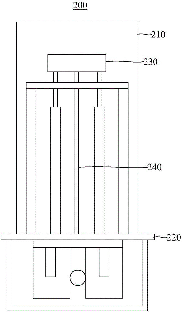
The invention discloses an ion source and an ion implantation device. The ion source has a vacuum chamber. The vacuum chamber comprises a plasma forming container, a first cathode arranged on one side of the plasma forming container and used for emitting electrons, a first indirectly-heated cathode, a second cathode arranged on the side of the plasma forming container opposite to the first cathode and used for emitting electrons, and a second indirectly-heated cathode, wherein the electrons emitted by the first cathode enter the plasma forming container after colliding the first indirectly-heated cathode, and the electrons emitted by the second cathode enter the plasma forming container after colliding the second indirectly-heated cathode. According to the ion source, when the first cathode or the second cathode is damaged, the ion source can continue to generate plasma only by changing the method of electrification of the first cathode and the second cathode, maintenance through opening the vacuum chamber is avoided, and the production efficiency is improved.

Description

technical field [0001] The invention relates to the technical field of semiconductors, in particular to an ion source and an ion implantation device. Background technique [0002] Ion beam thin film deposition and ion beam material modification are an important branch of material science. The research and promotion of ion beam technology has made great achievements. One of the signs is that ion implantation semiconductor doping has become a very large-scale integrated The key process of circuit microfabrication. Among them, the ion source is the key component to generate the required ions. [0003] figure 1 It is a schematic diagram of an ion source in the prior art, such as figure 1 As shown, the ion source 100 in the prior art includes a vacuum chamber 110 located on a support plate 120 . The vacuum chamber 110 has a plasma forming container 130 for generating ions inside, and an ionizable gas is introduced into the plasma forming container 130 from the outside of the ...

Claims


Application Information

Patent Timeline
IPC IPC(8): H01J37/08
CPCH01J37/08
Inventor 许飞秦斌汪东周智於鹏飞
Owner SEMICON MFG INT (SHANGHAI) CORP
Learn More