
Blade of a rotary flow machine with a radial strip seal

A technology of seals and blades, which is applied in the field of blades of swirl machines, can solve the problems of weakened cooling efficiency and other issues

Active Publication Date: 2015-03-18
ANSALDO ENERGIA SWITZERLAND AG
View PDF9 Cites 4 Cited by
  • Summary
  • Abstract
  • Description
  • Claims
  • Application Information

AI Technical Summary

Problems solved by technology

Cooling efficiency may also be impaired by hot gas entering the shank area from the hot gas path

Method used


Image

  • Blade of a rotary flow machine with a radial strip seal
  • Blade of a rotary flow machine with a radial strip seal
  • Blade of a rotary flow machine with a radial strip seal

Examples


Embodiment Construction

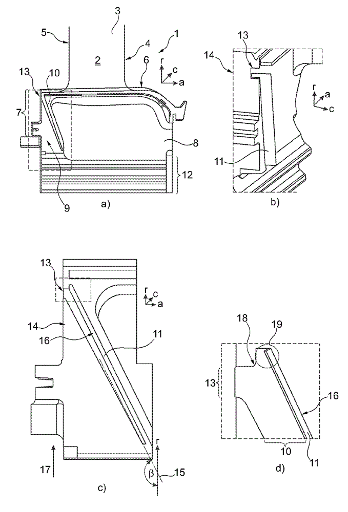
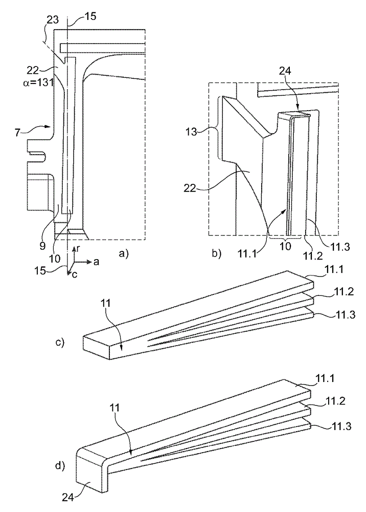
[0069] figure 1 A first embodiment of a blade 1 is illustrated, eg a moving low pressure turbine blade for a gas turbine arrangement. figure 1 a shows a side view in the circumferential direction c of a swirler (not shown) along a radially inner section of the blade 1 . figure 1 The axes shown in a mark the axial direction a, the radial direction r and the circumferential direction c of the swirl machine. Further description refers to the axes defined in the respective descriptions.

[0070] The blade 1 comprises an airfoil 2 having a suction surface 3 and a pressure surface (not shown) joined together along a leading edge 4 and a trailing edge 5 . The radially inwardly extending end of the airfoil 2 joins an inner platform 6 connecting the airfoil 2 to a shank 7 at the radial end of the airfoil 2 . The shank 7 has at least one tang socket 8 defined as a region recessed into the shank 7 which is parted by the axial a of the platform 6 and by at least one radially directed ...


PUM


Abstract

The invention refers to a blade (1) of a rotary flow machine comprising an airfoil (2) having a suction surface (3) and a pressure surface joining each other along a trailing and a leading edge (4, 5), a radially outward directed airfoil tip and a radially inward directed end joining an inner platform (6) connecting the airfoil to a shank (7) at a radial end of the airfoil and providing, at least one shank pocket (8) radially encircled by an axially extending portion of the platform and at least one radially extending rim (9) that extends from the trailing edge side of the shank and has an essentially radially orientated first slot (10) for receiving a seal (11), and a mount (12) extending radially inwardly from said shank pocket. Said first slot has a first aperture (13) on a shank surface orientated in an axial direction.

Description

technical field [0001] The invention relates to blades of cyclone machines. The blade includes an airfoil having suction and pressure surfaces joined together along a trailing and leading edge, a radially outwardly extending airfoil tip, and a radially inwardly extending end portion that An internal platform is attached that connects the airfoil to a shank at a radial end of the airfoil. The shank includes at least one shank pocket whose radially outwardly extending point is surrounded by a portion of the axially extending platform. At least one radially extending edge extends from the trailing edge side of the shank and has a radially oriented channel for receiving a seal. The mount extends radially inwardly from the socket. Background technique [0002] The blades of a swirl machine, such as a compressor unit or a turbine stage of a gas turbine arrangement, are typically arranged circumferentially on a plurality of axially ordered rotor wheels. The platform of each bla...

Claims


Application Information

Patent Timeline
IPC IPC(8): F01D5/14
CPCF01D11/006F01D5/30F05D2240/59F05D2250/75F05D2240/57F05D2260/30F05D2240/81F01D11/005F01D11/00
Inventor S.希文S.马瓦尼J.陶S.蒂博斯V.斯特发尼斯S.贾斯特R.科勒尔
Owner ANSALDO ENERGIA SWITZERLAND AG
Learn More