Double ventilation masonry wall

A masonry wall and double-layer technology, which is applied in the field of building wall structure, can solve the problems of harmful gas discharge, gas leakage, combustion, combustion explosion, etc., and achieve the effect of free space

Active Publication Date: 2015-03-18
CHINA IPPR INT ENG
View PDF7 Cites 0 Cited by
  • Summary
  • Abstract
  • Description
  • Claims
  • Application Information

AI Technical Summary

Problems solved by technology

[0003] When the heat source gas is heavier than air (such as propane), the situation is more complicated. These gases are heavier than air and are not volatile, and gas leakage and insufficient combustion will inevitably occur during production and use. If no measures are taken for it, the gas It will gradually accumulate near the ground of the plant, and when it accumulates to a certain concentration, there will be a danger of combustion and explosion when it encounters an open flame
[0004] At present, the commonly used solution is to exhaust the factory building with surface-mounted suction pipes indoors. The disadvantages of this are: 1. There will be many suction pipes in the factory building, which will affect the usable space of the factory building; 2. The pipes are all exposed in the workshop The side wall has a serious conflict with the rainwater pipe; 3. There are many air outlets connected to the outside, which will damage the overall aesthetic effect of the factory building
[0005] On the other hand, there are mainly two types of double-layer walls in China, one is double-layer curtain wall, the outside is generally glass curtain wall or metal plate curtain wall, the middle is an air layer, and the inner layer is generally glass curtain wall, stone curtain wall or masonry wall , the cost of this kind of wall is high, and it is rarely used in factories in China, and it is difficult to install equipment between double-layer curtain walls, which cannot solve the problem of timely discharge of harmful gases
The other is a composite sandwich wall, with masonry walls on both sides and an insulation layer (such as extruded polystyrene board) in the middle, combined to form an integral composite wall. This kind of wall has better thermal insulation performance than ordinary masonry walls, but it cannot solve the problem. ventilation problem

Method used


Image

  • Double ventilation masonry wall
  • Double ventilation masonry wall
  • Double ventilation masonry wall

Examples


Embodiment Construction

[0038] The technical solution of the present invention will be described in detail below in conjunction with the accompanying drawings and specific embodiments to further understand the purpose, solution and effect of the present invention, but it is not intended to limit the scope of protection of the appended claims of the present invention.

[0039] The double-layer ventilated masonry wall of the present invention is mainly suitable for the interior wall and exterior wall of industrial buildings, and is beneficial to solve the ventilation problem that cannot be solved by conventional methods.

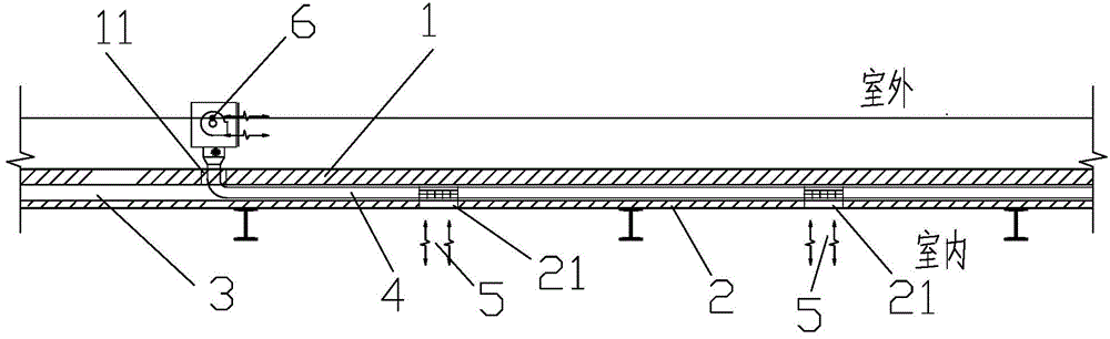
[0040] refer to figure 1 and figure 2 , which is a structural diagram of a double-layer ventilated masonry wall according to the first embodiment of the present invention. The double-layer ventilated masonry wall of this embodiment is used for the exterior walls of industrial buildings, and its main purpose is to discharge indoor dirty air to the outside, including The first wall b...


PUM


Abstract

The invention relates to a double ventilation masonry wall applied to interior walls or exterior walls for industrial buildings. The double ventilation masonry wall comprises a first wall, a second wall, a ventilation air layer, a ventilation pipeline, blowers and an exhaust fan. The ventilation layer is disposed between the first wall and the second wall; the ventilation pipeline is disposed in the ventilation air layer. The blowers are connected to the ventilation pipeline and are used for indoor / outdoor air into the ventilation pipeline. The exhaust fan is connected to a terminal of the ventilation pipeline and used for discharging the air sucked into the ventilation pipeline, to the outdoor / indoor. The double ventilation masonry wall has the advantages that the requirement for emission of dangerous gases is met, fresh air can be provided for a room needing the fresh air, space is reserved for laying other pipelines, production space is saved, a rain pipeline is avoided, and complete, flexible and free space is provided for production.

Description

technical field [0001] The invention relates to a building wall structure, in particular to a double-layer ventilation masonry wall which can solve the problem of ventilation. Background technique [0002] At present, in domestic industrial buildings, when the production heat source or radiant heating heat source is a gas lighter than air (such as natural gas), it is relatively easy to solve the problems encountered in the engineering design of plant ventilation and fire protection, which can be installed on the roof or Use external windows or install ventilators on the external wall to solve the problem. [0003] When the heat source gas is heavier than air (such as propane), the situation is more complicated. These gases are heavier than air and are not volatile, and gas leakage and insufficient combustion will inevitably occur during production and use. If no measures are taken for it, the gas It will gradually accumulate near the ground of the factory building. When it ...

Claims


Application Information

Patent Timeline
Patent Type & Authority Applications(China)
IPC IPC(8): E04B2/02F24F7/10
Inventor 毛绪前李侃张家珍
Owner CHINA IPPR INT ENG
Why Eureka
Try Eureka