
Method and apparatus for controlling printing sleeving alignment

A technology for controlling printing and printing conditions, applied in printing and other directions, can solve problems such as non-uniform encoding pulse signal, image overprint error, image error of four color surfaces, etc., and achieve the effect of improving printing quality

Inactive Publication Date: 2015-03-18
NEW FOUNDER HLDG DEV LLC +1
View PDF7 Cites 7 Cited by
  • Summary
  • Abstract
  • Description
  • Claims
  • Application Information

AI Technical Summary

Problems solved by technology

After printing is started, each print head module will use the corresponding start code pulse signal as the start print clock to start spraying. However, due to the error of the encoder itself and the error of the paper movement, the above is only The scheme of controlling each nozzle module to start printing with the corresponding start code pulse signal of the module will cause errors in the overprinting of the images of the four color planes; moreover, due to the different physical positions of each nozzle module, each nozzle module The clock used by the module when it starts printing is not the encoding pulse signal at the same time, and the encoding pulse signals at different times are not uniform, which will further cause errors in the overprinting of the images of the four color surfaces, thus affecting the print effect

Method used


Image

  • Method and apparatus for controlling printing sleeving alignment
  • Method and apparatus for controlling printing sleeving alignment
  • Method and apparatus for controlling printing sleeving alignment

Examples


Embodiment 1

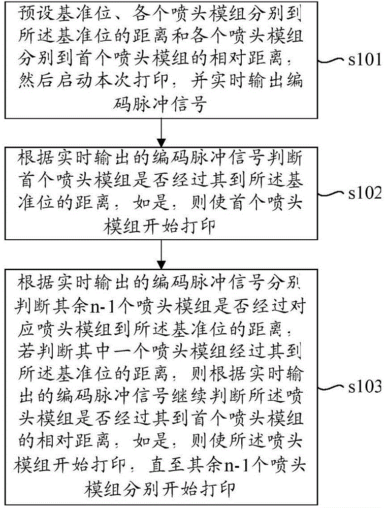
[0043] Such as figure 1 As shown, this embodiment provides a method for controlling printing registration, which is used to control the image synchronization of n color planes formed by n nozzle modules respectively, n is greater than 1, and the value of n depends on the color plane to be formed For example, YCMK four-color printing requires 4 nozzle modules, that is, n=4. The so-called image synchronization of n color planes refers to ensuring that n color planes of the same page are printed on the same position of the substrate to form a complete image on one page. The n nozzle modules are evenly arranged along the paper-feeding direction. Since the printing width in the direction perpendicular to the paper feeding direction (that is, the width of the page to be printed) is generally relatively wide, each nozzle module is generally composed of multiple small nozzles.

[0044] The method comprises the steps of:

[0045] s101. Preset the reference position, the distance fro...

Embodiment 2

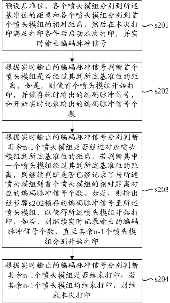
[0059] Such as image 3 As shown, the present embodiment provides a method for controlling printing registration, including the following steps:

[0060] s201. Preset the reference position, the distance from each nozzle module to the reference position and the relative distance from each nozzle module to the first nozzle module, and then start this printing after the printing conditions are met, and Real-time output of coded pulse signals; the first nozzle module refers to the nozzle module that first passes through the paper when the paper is fed.

[0061] Wherein, the method for judging whether the current printing meets the printing conditions is: judging whether the job has received imaging data, if yes, judging that the current printing meets the printing conditions, if not, judging that the current printing does not meet the printing conditions.

[0062] s202. According to the coded pulse signal output in real time, it is judged whether the first nozzle module has pass...

Embodiment 3

[0082] Such as Figure 5 As shown, this embodiment provides a method for controlling printing registration, which is used to control the image synchronization of the four color planes formed by the four spray head modules respectively. The four nozzle modules are evenly arranged along the paper-feeding direction. The first nozzle module refers to the nozzle module that first passes through the paper when the paper is fed. In this embodiment, the first nozzle module is represented by nozzle module 1, and the remaining 3 nozzle modules that pass through the paper in turn when the paper is fed are respectively It is represented by nozzle module 2, nozzle module 3 and nozzle module 4.

[0083] The method comprises the steps of:

[0084] s301. Start a job and prepare to start printing, so that each component returns to its working position.

[0085] s302. Preset the reference position, the distance from each nozzle module to the reference position, and the relative distance from...


PUM


Abstract

The invention provides a method for controlling printing sleeving alignment. The method comprises the following steps: 1), presetting a reference position, the distance from each nozzle module to the reference position and the relative distance of each nozzle module to an initial nozzle module, starting printing of this time, and outputting coding pulse signals in real time; 2), according to the coding pulse signals output in real time, determining whether the initial nozzle module passes through the distance from the initial nozzle module to the reference position, and if so, enabling the initial nozzle module to start printing; and 3), according to the coding pulse signals output in real time, respectively determining whether other n-1 nozzle modules pass through the distances from the corresponding nozzle modules to the reference position, if it is determined that one of the nozzle modules passes through the distance from itself to the reference position, continuing determining whether the nozzle module passes through the distance from itself to the initial nozzle module, and if so, enabling the nozzle module to start printing until the other n-1 nozzle modules respectively start printing. The invention correspondingly provides an apparatus for controlling printing sleeving alignment. According to the invention, the problem of unaligned sleeving printing of different color-surface images can be reduced.

Description

technical field [0001] The invention relates to the technical field of digital printing, in particular to a method and device for controlling printing alignment. Background technique [0002] Digital printing is a printing technology that has developed rapidly in recent years, and it uses the method of directly inputting, processing and printing data. The principle of digital printing equipment is: process the original data into dot matrix data through the host computer, process the dot matrix data into imaging data suitable for imaging through the control system, and then control the imaging components to directly image the imaging data. Among them, the workflow of digital printing equipment for on-demand inkjet printing is that, under the control of the control system, when the substrate (such as paper) reaches a predetermined position, the piezoelectric crystal in the imaging component is controlled to generate pulses to send the nozzle module The ink in the process is e...

Claims


Application Information

Patent Timeline
Patent Type & Authority Applications(China)
IPC IPC(8): B41J2/07
Inventor 李丹温晓辉刘志红
Owner NEW FOUNDER HLDG DEV LLC
Learn More