Shockproof colloid mill

A technology of colloid mill and anti-vibration pad, which is applied in the field of mechanical processing, and can solve problems such as the easy displacement of the mill body

Inactive Publication Date: 2015-03-18
张丹
View PDF0 Cites 1 Cited by
  • Summary
  • Abstract
  • Description
  • Claims
  • Application Information

AI Technical Summary

Problems solved by technology

[0004] The invention solves the problem that the mill body is prone to displacement during processing and improves the processing stability by setting an anti-vibration colloid mill

Method used


Image

  • Shockproof colloid mill

Examples


Embodiment 1

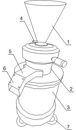
[0020] Such as figure 1 As shown, this embodiment includes a grinding head 2, a feed port 1, a discharge port and a driving mechanism, the feeding port 1 is arranged on the grinding head 2, the driving mechanism is connected with the grinding head 2, and the discharge port is set At the bottom of the grinding head 2, an insert 4 is provided at the bottom of the feed port 1, and the insert 4 is movably arranged at the bottom of the feed port 1; a plurality of anti-vibration feet 7 are also provided at the bottom of the driving mechanism. When working, the material enters the grinding head 2 through the feed port 1, and starts a series of dispersion, crushing, emulsification, homogenization, and uniform mixing operations under the drive of the driving mechanism; there is an insert 4 at the bottom of the feed port, The speed of material leakage in the feed port 1 can be adjusted according to the specific situation. When the insert 4 moves outward, the gap between the feed port 1 ...

Embodiment 2

[0023] Such as figure 1 As shown, this embodiment is based on Embodiment 1, and the discharge port includes an upper nozzle 5 and a lower nozzle 6, and the upper nozzle 5 and the lower nozzle 6 are connected. After a series of dispersing, crushing, emulsifying, homogenizing and uniform mixing operations are completed, the material is discharged from the discharge port. The discharge port is divided into an upper nozzle 5 and a lower nozzle 6. The connection between the upper nozzle 5 and the lower nozzle 6 forms an obtuse angle arc. When the material is thrown out of the discharge port due to inertia, the upper nozzle 5 will carry the material itself The impulsive force buffered is discharged by lower mouth 6 again.

Embodiment 3

[0025] Such as figure 1 As shown, the present embodiment is based on the embodiment 2, and the lower nozzle 6 includes a lower nozzle groove and a groove cover, and the groove cover is connected with the lower nozzle groove by bolts. The upper mouth 5 will accumulate a certain amount of material layer due to the mill working for a long time, if it is not cleaned regularly, it will also cause the discharge port to be blocked. The lower nozzle groove and the groove cover are connected by bolts, and the material residue in the upper nozzle 5 and the lower nozzle 6 can be cleaned well only by opening the groove cover during cleaning.


PUM


Abstract

The invention discloses a shockproof colloid mill which comprises a grinding head, a feeding hole, a discharging hole and a drive mechanism, wherein the feeding hole is formed in the grinding head, the drive mechanism is connected with the grinding head, the discharging hole is formed in the bottom of the grinding head, an insertion sheet is arranged at the bottom of the feeding hole, and movably arranged at the bottom of the feeding hole; a plurality of shockproof food pads are arranged at the bottom of the drive mechanism. During machining, a material enters in the grinding head through the feeding hole, a series of dispersing, crushing, emulsifying, homogenizing and uniform-mixing operations are started to be performed under the drive of the drive mechanism; because a device in the grinding head runs at a high speed, small shocking of the mill is caused. The plurality of shockproof food pads at the bottom of a supporting frame can be used for relieving the shocking generated by the mill per se, so that displacement or swinging is prevented from occurring in a machining process of the mill, and procedures such as dispersing, crushing, emulsifying, homogenizing and uniform-mixing are enabled to be stably performed.

Description

technical field [0001] The invention relates to the field of mechanical processing, in particular to an anti-vibration colloid mill. Background technique [0002] The colloid mill belongs to ultrafine pulverization equipment, which has the functions of crushing, emulsification, dispersion, stirring, etc., and can replace stone mills, sand mills, ball mills, tissue grinders, etc. Colloid mills can also be used for homogenization. Generally speaking, its refinement effect is weaker than that of the homogenizer, but it has a strong adaptability to materials, so in many occasions, it is used in the front of the homogenizer or in high-viscosity occasions. When there are many substances, colloid mills are often used for refinement. [0003] At present, the colloid mills used on the market often have a very fast cutting speed due to the requirements of processing efficiency. However, this method also has certain defects: the material is easy to block at the feed port; the proces...

Claims


Application Information

Patent Timeline
Patent Type & Authority Applications(China)
IPC IPC(8): B02C23/02B02C23/00
CPCB02C23/02B02C23/00
Inventor 张丹
Owner 张丹
Why Eureka
Try Eureka