
Staring super-resolution imaging device and method

A super-resolution and imaging device technology, applied in TV, color TV, image communication, etc., can solve the problems of poor reconstruction effect, poor versatility, complex process, etc., and achieve the effect of low cost, enhanced stability, and simple process

Inactive Publication Date: 2015-03-11
XIDIAN UNIV
View PDF8 Cites 10 Cited by
  • Summary
  • Abstract
  • Description
  • Claims
  • Application Information

AI Technical Summary

Problems solved by technology

[0005] The purpose of the present invention is to overcome the defects of poor versatility, complex process, and poor reconstruction effect in the prior art, and provides a staring super-resolution imaging device and method, which obtains multiple frames of images by randomly moving the detector, and is used for Solve the problem of low resolution of existing imaging devices

Method used


Image

  • Staring super-resolution imaging device and method
  • Staring super-resolution imaging device and method
  • Staring super-resolution imaging device and method

Examples


Embodiment Construction

[0042] In order to make the purpose of the present invention, the technical problem to be solved and the technical solution clearer, the present invention will be further described in detail below in conjunction with the accompanying drawings.

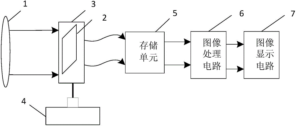
[0043] refer to figure 1 , the present invention includes imaging device lens group 1, detector 2, detector driving platform 3, driver 4, storage unit 5, image processing circuit 6 and image display circuit 7; in order to ensure that detector 2 can successfully receive images and communicate with detection The detector drive platform 3 moves synchronously. The detector 2 is located on the optical path of the lens group 1 of the imaging device and in its focal plane. The detector 2 adopts a charge-coupled device CCD or a complementary metal-oxide semiconductor CMOS or a charge injection device CID, fixed Before the detector driving platform 3; the driver 4 can be a piezoelectric ceramic driver, which is arranged on one side of the detec...


PUM


Abstract

The invention provides a staring super-resolution imaging device and method, and aims at solving the problem of low resolution of an existing imaging device. The device comprises an imaging device lens group (1), a detector (2), a detector driving platform (3), a driver (4), a storage device (5), an image processing circuit (6) and an image display circuit (7), wherein the detector (2) is arranged in a focal plane on a light path of the imaging device lens group (1); a drive part of the driver (4) drives the detector driving platform (3) to generate movement with magnitude and direction being random values. The imaging method comprises the following realization steps: a change number instruction is set; the driver (4) drives the detector (2) to do corresponding number of random jitter; a light signal is imaged on the detector (2) through the imaging device lens group (1) to obtain a low-resolution image with a frame number corresponding to a change number; the low-resolution image is rebuilt by the utilization of a variational Bayesian algorithm. The staring super-resolution imaging device and method are suitable for video reconstruction and satellite photography.

Description

technical field [0001] The invention belongs to the technical field of super-resolution imaging, and in particular relates to a staring super-resolution imaging device and imaging method for multi-frame image acquisition and reconstruction, which can be used for video reconstruction and satellite shooting. Background technique [0002] Improving the resolution of the optical imaging system is the relentless pursuit of image science research and its engineering applications. In addition to improving the resolution by improving the performance of imaging system-related components, such as optical system focal length, aperture and detectors, you can also choose Adding suitable optical devices to the imaging system can improve the resolution, but adjusting the structure of the imaging system will lead to the complexity of the system and a large increase in tasks to a certain extent, so how to restore or reconstruct super-resolution based on existing imaging equipment Image has b...

Claims


Application Information

Patent Timeline
IPC IPC(8): H04N5/232G06T5/00
Inventor 邵晓鹏王怡许洁刘飞杜鹃
Owner XIDIAN UNIV
Learn More