
Multi-bandpass filter based on multimode resonator

A multi-mode resonance and multi-passband technology, which is applied in the direction of resonators, waveguide devices, electrical components, etc., can solve the unsatisfactory filter passband selectivity, the influence of the signal integrity of the ground plane, and the insertion loss of the filter Major problems, to achieve the effect of improving out-of-band characteristics, increasing flexibility and freedom, and simplifying complexity

Active Publication Date: 2015-03-11
XIDIAN UNIV
View PDF3 Cites 17 Cited by
  • Summary
  • Abstract
  • Description
  • Claims
  • Application Information

AI Technical Summary

Problems solved by technology

[0003] In order to meet this demand, a lot of research work has been devoted to the design of multi-passband filters. In May 2010, Cheng, C.-M. et al. published a four-dimensional structure implemented with a defect ground structure in the journal IEEE MICROWAVE AND WIRELESS COMPONENTS LETTERS. Passband filter, however, the defective ground structure will affect the integrity of the ground plane signal when the filter is packaged; Hung-Wei, W. and Y.Ru-Yuan in IEEE MICROWAVE AND WIRELESS COMPONENTS LETTERS in April 2011 A four-pass band filter realized by using asymmetric ladder impedance resonators was published on the Internet, but the size of the circuit becomes larger due to the use of more resonators in its design; in July 2012, Chi-Feng Chen presented at IEEE MICROWAVE The AND WIRELESS COMPONENTS LETTERS journal published a five-frequency filter based on a three-mode stub load ladder impedance resonator, but the insertion loss of the filter is too large, which affects its application; in September 2013, J.Xu et al. published in IEEE TRANSACTIONS ON MICROWAVE Several multi-passband filters designed with open-circuit stub-loaded ladder impedance resonators were published in THEORY AND TECHNIQUES journals, but the selectivity of the filter passbands is not satisfactory

Method used


Image

  • Multi-bandpass filter based on multimode resonator
  • Multi-bandpass filter based on multimode resonator
  • Multi-bandpass filter based on multimode resonator

Examples


no. 1 example

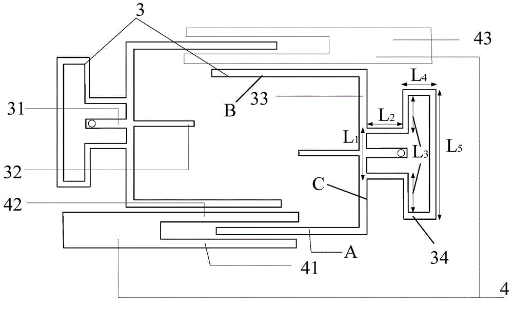
[0026] The first embodiment: design a four-pass band filter with a size of 27.5mm×23mm.

[0027] refer to figure 1 and figure 2 , The four-pass band-pass filter of the present invention is mainly composed of a microstrip dielectric substrate 1, a metal ground plate 2, a resonator 3, an input and output feeder 4, and a ground hole 5. in:

[0028] The microstrip dielectric substrate 1 adopts a double-sided copper-clad laminate with a dielectric constant of 2.2 and a thickness of 1.0 mm. The metal ground plate 2 is placed under the double-sided copper-clad laminate, and the four-mode resonator 3 is placed above the double-sided copper-clad laminate. Input and output feeders 4 and ground hole 5. in:

[0029] The input-output feeder 4 is made up of a pair of aligned interdigital coupling feeders, and each feeder includes two interdigital stubs 41, 42 and a section of 50 ohm microstrip line 43; the interdigital stubs 41, 42 are connected in parallel on the 50 ohm The same end ...

no. 2 example

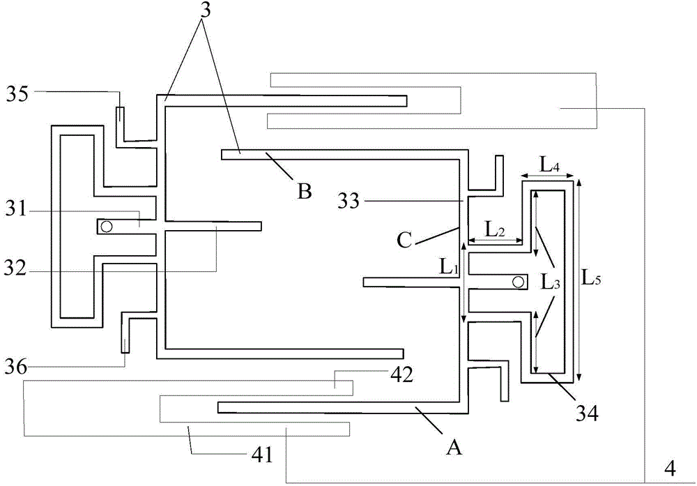
[0034] The second embodiment: design a five-pass band filter with a size of 29mm×22.9mm.

[0035] refer to image 3 and Figure 4 , The five-pass bandpass filter of the present invention is mainly composed of a microstrip dielectric substrate 1, a metal ground plate 2, a resonator 3, an input and output feeder 4, and a ground hole 5. in:

[0036] The microstrip dielectric substrate 1 adopts a double-sided copper-clad laminate with a dielectric constant of 2.2 and a thickness of 1.0mm. The metal ground plate 2 is placed under the double-sided copper-clad laminate, and the five-mode resonator 3 is placed above the double-sided copper-clad laminate. Input and output feeders 4 and ground hole 5. in:

[0037]The input and output feeder 4 is composed of a pair of aligned interdigital coupling feeders, and each feeder includes two interdigital stubs 41, 42 and a section of 50 ohm microstrip line 43; the interdigital stubs 41, 42 are connected in parallel at 50 ohm The same end o...


PUM

PropertyMeasurementUnit
Total lengthaaaaaaaaaa

Abstract

The invention discloses a multi-bandpass filter based on a multimode resonator and mainly solves the problem of large size and poor performance of the multi-bandpass filter. The multi-bandpass filter based on the multimode resonator comprises a micro-strip dielectric substrate (1), a metal earth plate (2), a resonator (3) and an input-output feeder line (4). The resonator (3) is composed of two identical five-mode resonators which are staggered, each five-mode resonator is composed of a short-circuit branch (31), an open-circuit branch (32), a U-shaped microstrip line (33), a bulged loop (34) and L-shaped open-circuit branches (35 and 36). The symmetric center of the bulged loop (34) is superposed with that of the U-shaped microstrip line, and the top end of the bulged loop is connected with the bottom end of the U-shaped microstrip line. The L-shaped open-circuit branches are connected at the bottom end of the U-shaped microstrip line. The input-output feeder line (4) is composed of a pair of quasi fork-finger type coupled feeder lines. The size of the multi-bandpass filter can be reduced, design complexity is reduced, bandpass selectivity is improved, and the multi-bandpass filter can be used for a wireless communication system.

Description

technical field [0001] The invention belongs to the technical field of electronic devices, and in particular relates to the design of a microstrip multi-passband filter, which can be used for a radio frequency front end of a wireless communication system. Background technique [0002] Microwave filters are an indispensable and important part of communication systems, radar systems, and measurement systems. Therefore, microwave filters have always been the focus and hotspot of wireless communication system research. Modern wireless communication systems require radio frequency devices to work in multiple separate frequency bands to meet the needs of a multi-mode terminal to achieve different services, and transmit frequency signals of multiple discontinuous channels through one beam. This requires the use of multi-passband filters to suppress spurious noise signals. In the past, in order to realize multi-band communication, each frequency band required an independent filter,...

Claims


Application Information

Patent Timeline
IPC IPC(8): H01P1/203H01P7/00
Inventor 魏峰丁晨李姣王新怀史小卫
Owner XIDIAN UNIV
Learn More