Eureka AIR delivers breakthrough ideas for toughest innovation challenges, trusted by R&D personnel around the world.

Flue gas water recycling system

A water recovery and flue gas technology, applied in water shower coolers, combustion methods, indirect carbon dioxide emission reduction, etc., can solve the problems of large volume and cost of flue gas coolers, large heat exchange temperature difference, etc., and achieve efficient and low-cost recovery , the effect of reducing costs

Inactive Publication Date: 2015-03-11
UNIV OF SHANGHAI FOR SCI & TECH
View PDF6 Cites 4 Cited by
  • Summary
  • Abstract
  • Description
  • Claims
  • Application Information

AI Technical Summary

Problems solved by technology

Compared with water as the cooling medium, the advantages of using ambient air as the cooling medium are: the ambient air is convenient and easy to get without geographical restrictions, the air cooling technology is mature, and there is no corrosion and dirt on the air side of the heat exchanger; the ambient air is used as the cooling medium. The disadvantage is that the flue gas cooler using ambient air as the cooling medium has a large volume and cost, and because the flue gas often contains acidic and corrosive gases, the heating surface of the low-temperature flue gas cooler must be made of expensive corrosion-resistant steel , which makes the disadvantages of the technical solution of directly cooling the flue gas by air more prominent
This is because the heat transfer temperature difference between the flue gas above 100°C and the cooling medium is relatively large, so it is relatively easy to recover a part of the waste heat of the flue gas by cooling the flue gas through a certain process; however, to realize the recovery of flue gas water at the same time, It is necessary to cool the flue gas below the water dew point of the flue gas (the common water dew point of the flue gas is between 45 and 55°C), which requires a large amount of cooling medium with a very low temperature, and most industrial energy consumption systems do not have the ability to do so Conditions for cooling low-temperature flue gas

Method used


Image

  • Flue gas water recycling system
  • Flue gas water recycling system
  • Flue gas water recycling system

Examples


Embodiment Construction

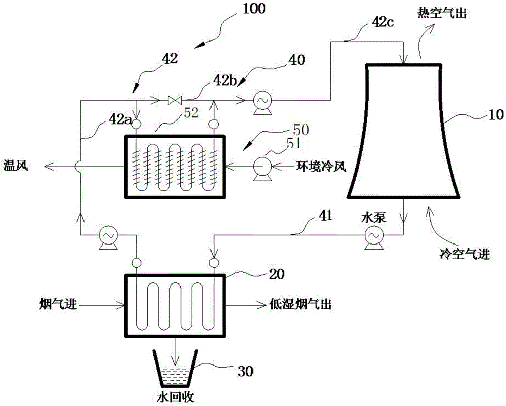
[0019] In order to make the technical means, creative features, goals and effects of the present invention easy to understand, the following embodiments describe the flue gas water recovery system involved in the present invention in detail in conjunction with the accompanying drawings and embodiments.

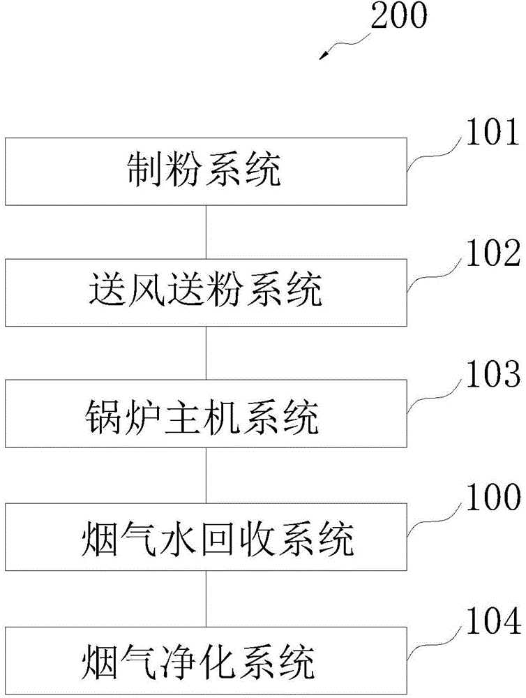
[0020] figure 1 It is a structural block diagram of the boiler system in the embodiment of the present invention.

[0021] Such as figure 1 As shown, the boiler system 200 is used to burn coal to generate a large amount of flue gas, which contains moisture, especially the flue gas generated by burning high-moisture coal as fuel has a relatively high moisture content.

[0022] The boiler system 200 includes: a flue gas water recovery system 100 , a powder making system 101 , an air and powder feeding system 102 , a boiler host system 103 and a flue gas purification system 104 . The pulverizing system 101 is used to provide pulverized coal, the air pulverized powder supply sys...


PUM


Abstract

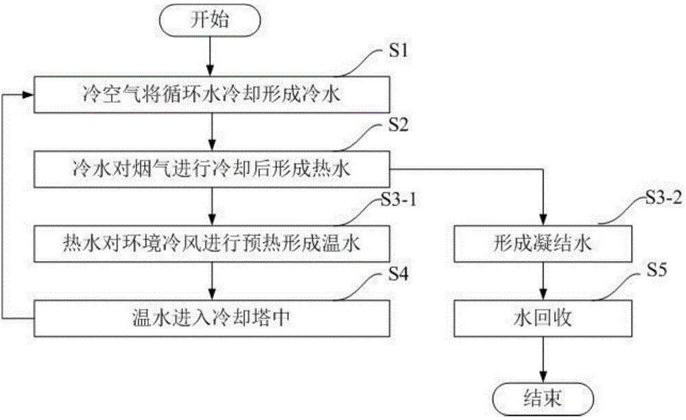
The invention discloses a flue gas water recycling system used for recycling the water after cooling the flue gas discharged from the combustion apparatus. The flue gas water recycling system comprises a cooling tower; a flue gas cooler, a condensation water recovery device and a water circulation device, which comprises a first pipeline used for transporting the cold water into the flue gas cooler, and a second pipeline connected with the inlet of the flue gas cooler and the outlet of the cooling tower and used for transporting the circulation water for the cooling tower, wherein the circulation water is cooled into the cold water by the cold air in the cooling tower, the cold water flows into the flue gas cooler through the first pipeline for cooling the flue gas and changes into the hot water, the hot water passes through the second pipeline for forming the warm water, the warm water flows into the cooling tower for circulation, the cold water cools the flue gas in the flue gas cooler, the water in the flue gas condenses into the condensation water, and the condensation water is recovered by the condensation water recovery device. The flue gas water recycling system can recycle the water in the flue gas discharged from the combustion apparatus at high efficiency and low cost.

Description

technical field [0001] The invention belongs to the field of flue gas waste heat and water recovery, and in particular relates to a flue gas water recovery system which recovers water after cooling the flue gas discharged from a combustion device. Background technique [0002] At present, the flue gas of various boilers and kilns contains a large amount of water resources, especially the moisture content of the flue gas produced by natural gas and high-moisture coal as fuel is relatively high, and the volumetric share of water vapor can reach more than 15%. . However, my country is a country with severe drought and water shortage. The per capita share of water resources is only 1 / 4 of the world's average level, ranking 121st in the world. Moreover, the distribution of water resources in my country is extremely uneven. The area accounts for 63.5%, and the water resources only account for 19% of the country's total, but more than 85% of my country's coal, oil and natural gas r...

Claims


Application Information

Patent Timeline
IPC IPC(8): F23J15/06F23L15/00F28C1/00
CPCY02E20/34
Inventor 马有福杨丽娟岳荣
Owner UNIV OF SHANGHAI FOR SCI & TECH
Why Eureka
Eureka Blog
Learn More