
A liquid flow go-stop gauge

A go-no-go gauge and flow rate technology, which is applied in the field of flow limiting valves, can solve the problems of inability to meet the requirements of online detection, high cost of use, and low safety factor, and achieve simple and intuitive discrimination methods, reduce detection costs, and improve safety. Effect

Active Publication Date: 2019-10-08
常州博瑞油泵油嘴有限公司
View PDF6 Cites 0 Cited by
  • Summary
  • Abstract
  • Description
  • Claims
  • Application Information

AI Technical Summary

Problems solved by technology

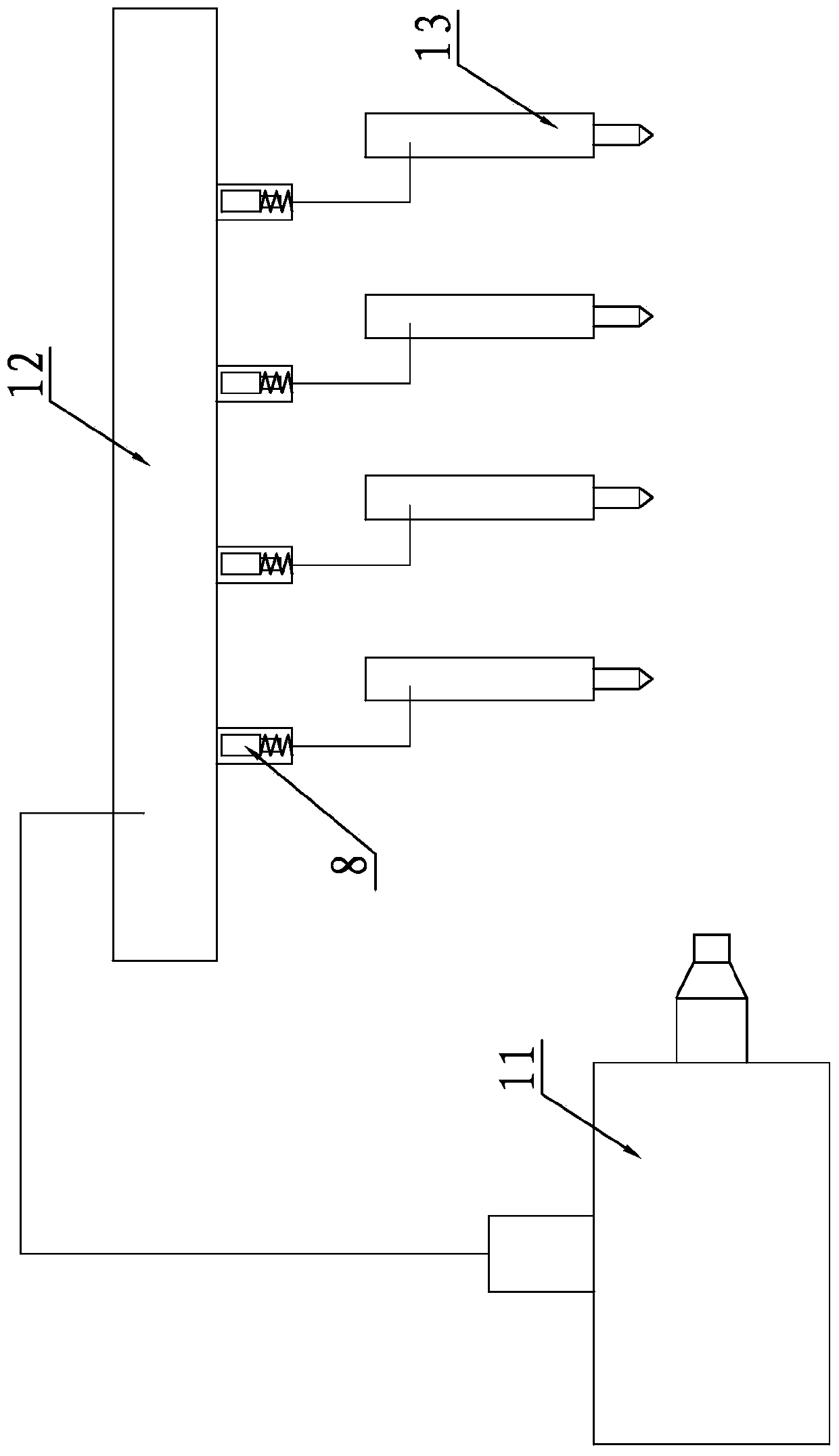
[0007] First, the investment in testing equipment is large, and the cost of testing is high. The value of a single fuel injection gauge alone is more than 300,000 yuan, and it cannot meet the requirements of online testing in the mass production process;
[0008] Second, a special high-flow common rail injector 13 is used as an indirect measurement device. Due to the need for continuous start and stop during the test, the loss of the injector 13 is serious. Because the value of the common rail injector 13 itself is relatively high, about 2000 Yuan / piece, so the use cost is too high;
[0009] Third, after the fuel injector 13 is used for a long time, the fuel injection characteristics of the fuel injector 13 will change, and the return flow will increase, resulting in inaccurate test results;
[0010] Fourth, since the fuel injector 13 is used as the flow regulating device, the system needs to maintain a high pressure to ensure that the instantaneous flow of the fuel injector 13 meets the closing requirements of the restrictor 8, and the system safety factor is low

Method used


Image

  • A liquid flow go-stop gauge
  • A liquid flow go-stop gauge
  • A liquid flow go-stop gauge

Examples


specific Embodiment approach

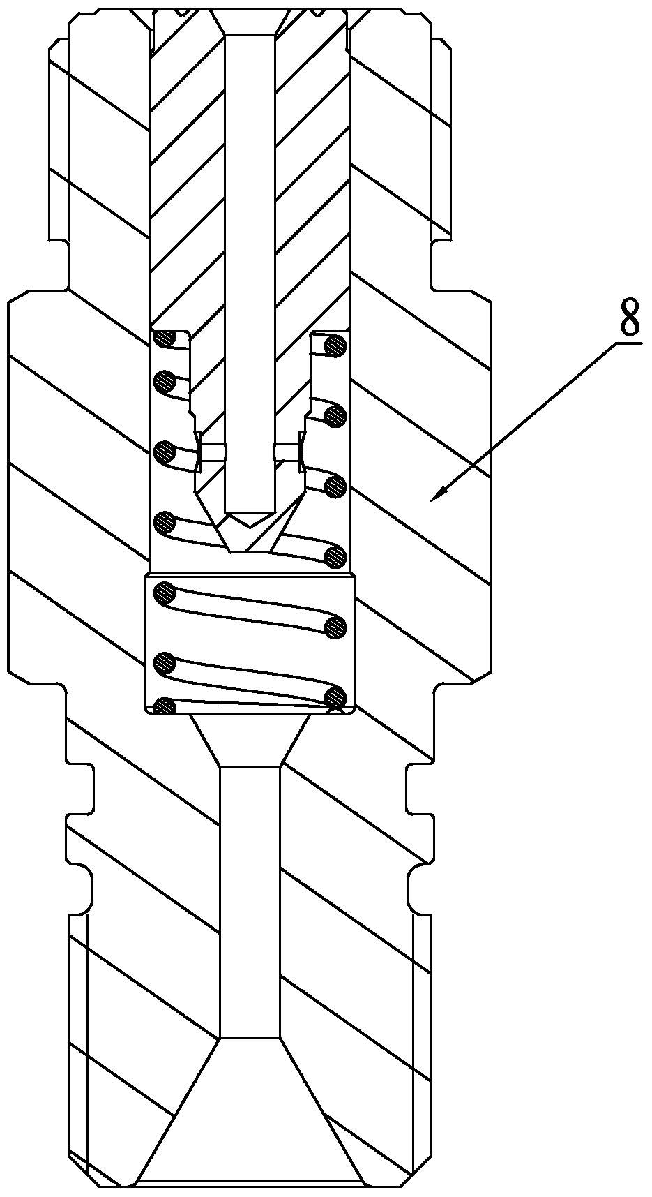
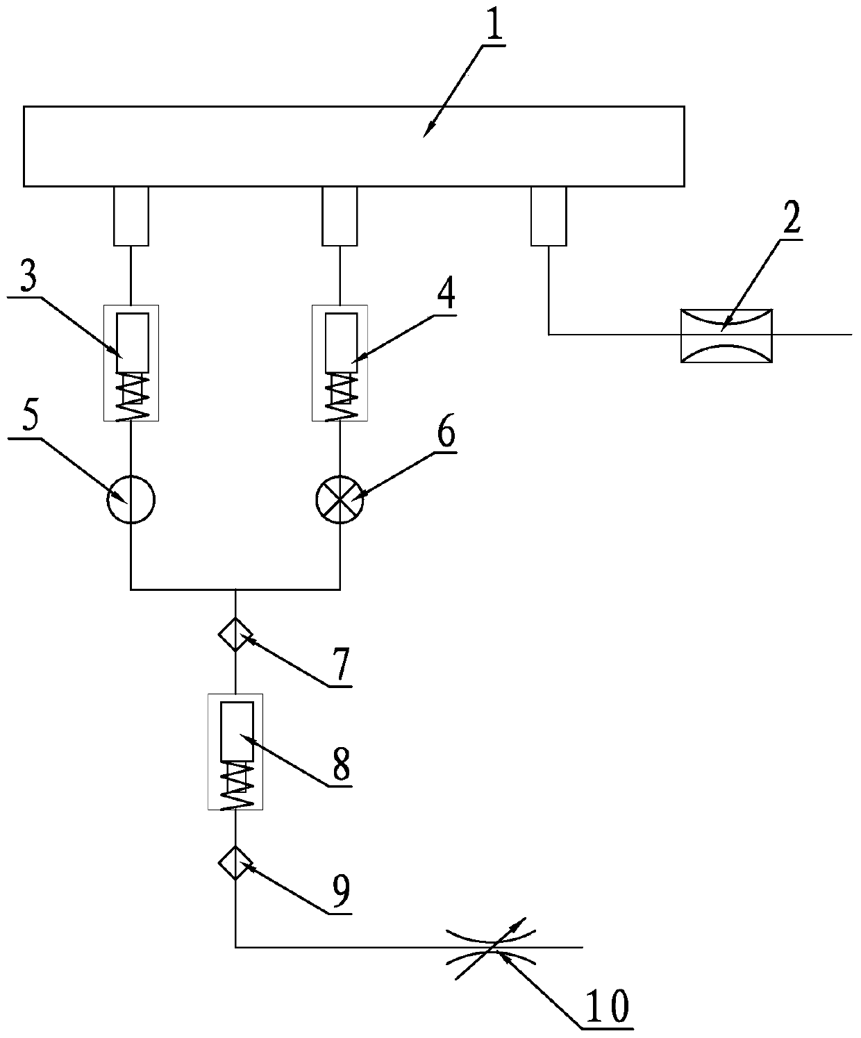
[0029] A liquid flow go-no-go gauge, such as image 3As shown, it consists of accumulator 1, safety valve 2, upper limit restrictor 3, lower limit restrictor 4, left stop valve 5, right stop valve 6, upper pressure sensor 7, current limiter to be tested 8, lower pressure The sensor 9 and the flow regulating valve 10 are composed, the safety valve 2 is connected with the accumulator 1, the left cut-off valve 5 is connected with the accumulator 1 after being connected in series with the upper limit flow limiter 3, and the right cut-off valve 6 is connected with the lower limit flow limiter 4 After being connected in series with the accumulator 1, the upper end of the upper pressure sensor 7 is connected with the left shut-off valve 5 and the right shut-off valve 6 at the same time, and the lower end of the upper pressure sensor 7 is connected with the oil inlet end of the flow limiter 8 to be tested. The oil outlet end of the detection flow limiter 8 is connected to the lower pr...


PUM


Abstract

The invention discloses a liquid flow go-no go gauge, which comprises an energy storage device, a safety valve, an upper limit flow limiter, a lower limit flower limiter, a left stop valve, a right stop valve, an upper pressure sensor, a flow limiter to be detected, a lower pressure sensor and a flow regulation valve, wherein the safety valve is communicated with the energy storage device; the left stop valve is communicated with the energy storage device after being connected in series with the upper limit flow limiter; the right stop valve is communicated with the energy storage device after being connected in series with the lower limit flow limiter; the upper end of the upper pressure sensor is simultaneously communicated with the left stop valve and the right stop valve, and the lower end of the upper pressure sensor is connected with the oil inlet end of the flow limiter to be detected; the oil outlet end of the flow limiter to be detected is connected with the lower pressure sensor; the lower pressure sensor is communicated with the flow regulation valve. The liquid flow go-no go gauge is simple in structure, low in construction cost, economical and practical, all flow limiters can be detected on line, the detection cost can be lowered, and a judgment method is simple and direct; meanwhile, a system can run under lower pressure, difficulty in implementation is greatly lowered, and the safety is greatly improved.

Description

Technical field: [0001] The invention relates to a flow limiting valve in a high-pressure common rail system of a diesel engine, in particular to a rapid detection device for accurately and simply detecting the flow rate of the flow limiting valve. Background technique: [0002] With the development of the national economy, automobiles have entered ordinary families in China. At present, the number of civilian automobiles has exceeded 12 million, of which diesel vehicles account for a large proportion; Energy saving and emission reduction indicators put forward higher requirements. At present, my country has begun to implement the National IV emission standards and new fuel standards, requiring the fuel supply system to provide diesel engines with precisely timed and quantitative fuel in a higher pressure and more flexible manner, which means that the old mechanical fuel injection The system can no longer meet the new requirements. At the same time, the advantages of the di...

Claims


Application Information

Patent Timeline
Patent Type & Authority Patents(China)
IPC IPC(8): F02M65/00
Inventor 沙有胜汤曌庄福如蒋岳群赵俊鹏陈苇
Owner 常州博瑞油泵油嘴有限公司
Learn More