Liquid flow go-no go gauge
A technology of pass and stop gauge and flow, applied in the field of restrictor valve, can solve the problems of inability to meet the requirements of on-line detection, high cost of use, low safety factor, etc. Effect
- Summary
- Abstract
- Description
- Claims
- Application Information
AI Technical Summary
Problems solved by technology
Method used
Image
Examples
specific Embodiment approach
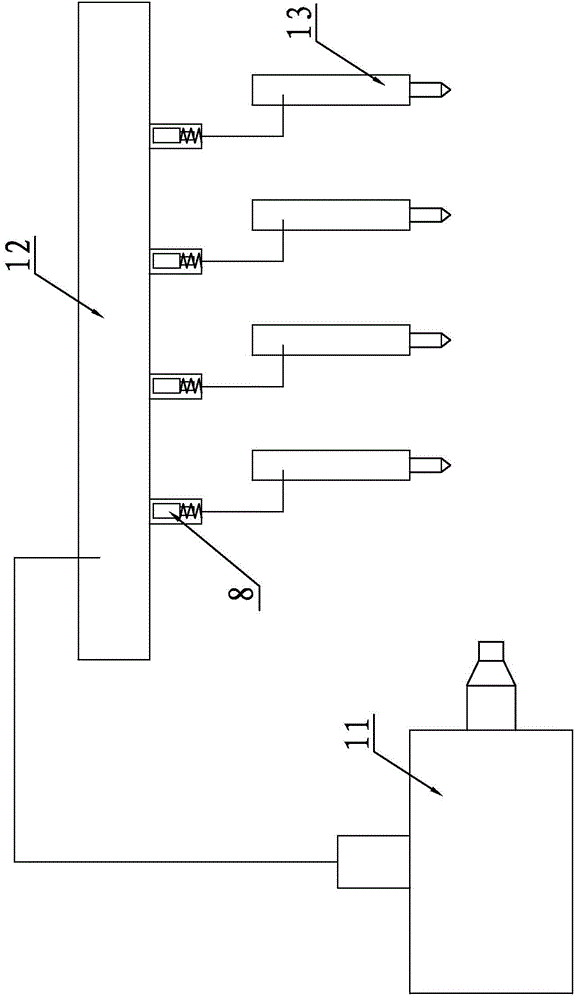
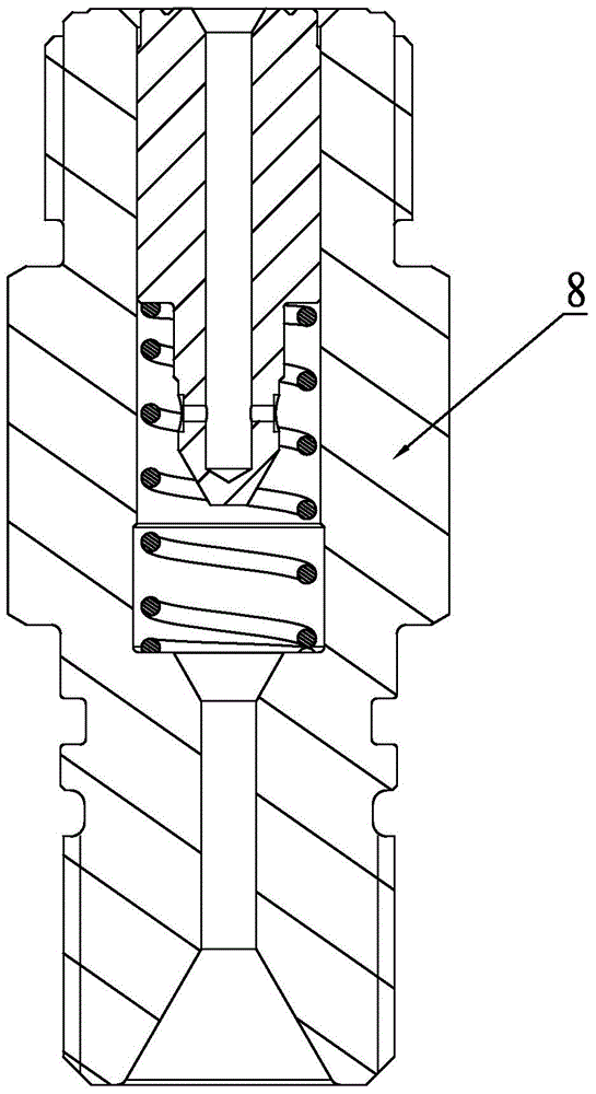
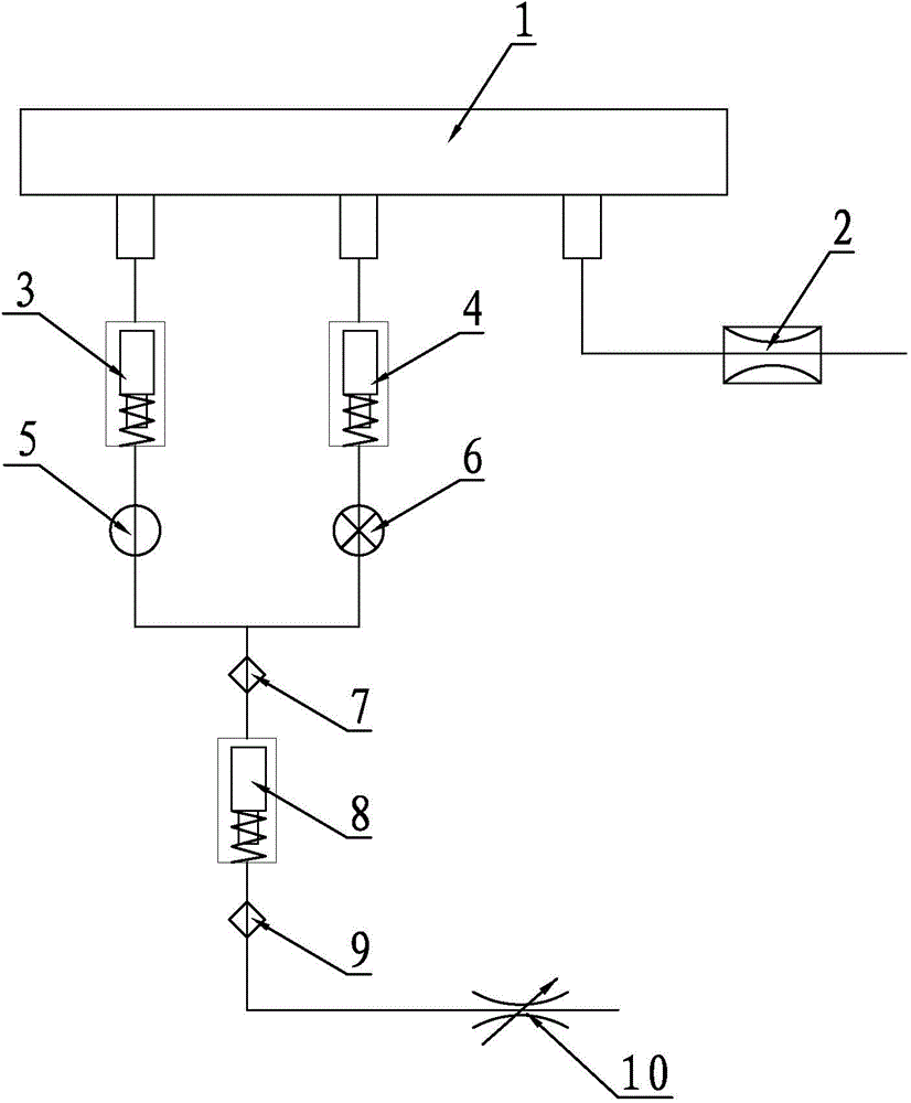
[0029] A liquid flow go-no-go gauge, such as image 3As shown, it consists of accumulator 1, safety valve 2, upper limit restrictor 3, lower limit restrictor 4, left stop valve 5, right stop valve 6, upper pressure sensor 7, current limiter to be tested 8, lower pressure The sensor 9 and the flow regulating valve 10 are composed, the safety valve 2 is connected with the accumulator 1, the left cut-off valve 5 is connected with the accumulator 1 after being connected in series with the upper limit flow limiter 3, and the right cut-off valve 6 is connected with the lower limit flow limiter 4 After being connected in series with the accumulator 1, the upper end of the upper pressure sensor 7 is connected with the left shut-off valve 5 and the right shut-off valve 6 at the same time, and the lower end of the upper pressure sensor 7 is connected with the oil inlet end of the flow limiter 8 to be tested. The oil outlet end of the detection flow limiter 8 is connected to the lower pr...
PUM
 Abstract
Description
Claims
Application Information
 - R&D
- Intellectual Property
- Life Sciences
- Materials
- Tech Scout
- Unparalleled Data Quality
- Higher Quality Content
- 60% Fewer Hallucinations
Browse by: Latest US Patents, China's latest patents, Technical Efficacy Thesaurus, Application Domain, Technology Topic, Popular Technical Reports.
© 2025 PatSnap. All rights reserved.Legal|Privacy policy|Modern Slavery Act Transparency Statement|Sitemap|About US| Contact US: help@patsnap.com


