
A self-locking mechanical lock relying on gravity

A self-locking, mechanical lock technology, applied in the field of mechanical locks, can solve problems such as the safety and stability of the ratchet mechanism, the locking and unlocking of difficult locking mechanisms, mechanical fatigue and mechanical wear, and achieve simplified locking and unlocking The process, the bite is firm, and the effect of improving the service life

Active Publication Date: 2017-06-16
NORTHEASTERN UNIV LIAONING
View PDF5 Cites 0 Cited by
  • Summary
  • Abstract
  • Description
  • Claims
  • Application Information

AI Technical Summary

Problems solved by technology

[0002] The existing self-locking mechanical locks are mainly ratchet mechanisms and their deformation forms. The disadvantages are: it is difficult to realize the locking and unlocking of the locking mechanism within a small stroke range, and the unlocking of the ratchet mechanism is difficult to achieve through a simple structure; When the mechanism is locked, it mainly relies on gear self-locking and friction self-locking. The former is often used in conjunction with springs. As the use time increases, due to the hazards of mechanical fatigue and mechanical wear, the safety and stability of the ratchet mechanism are greatly improved. decline

Method used


Image

  • A self-locking mechanical lock relying on gravity
  • A self-locking mechanical lock relying on gravity
  • A self-locking mechanical lock relying on gravity

Examples


Embodiment Construction

[0016] The present invention will be further described below in conjunction with the accompanying drawings and embodiments.

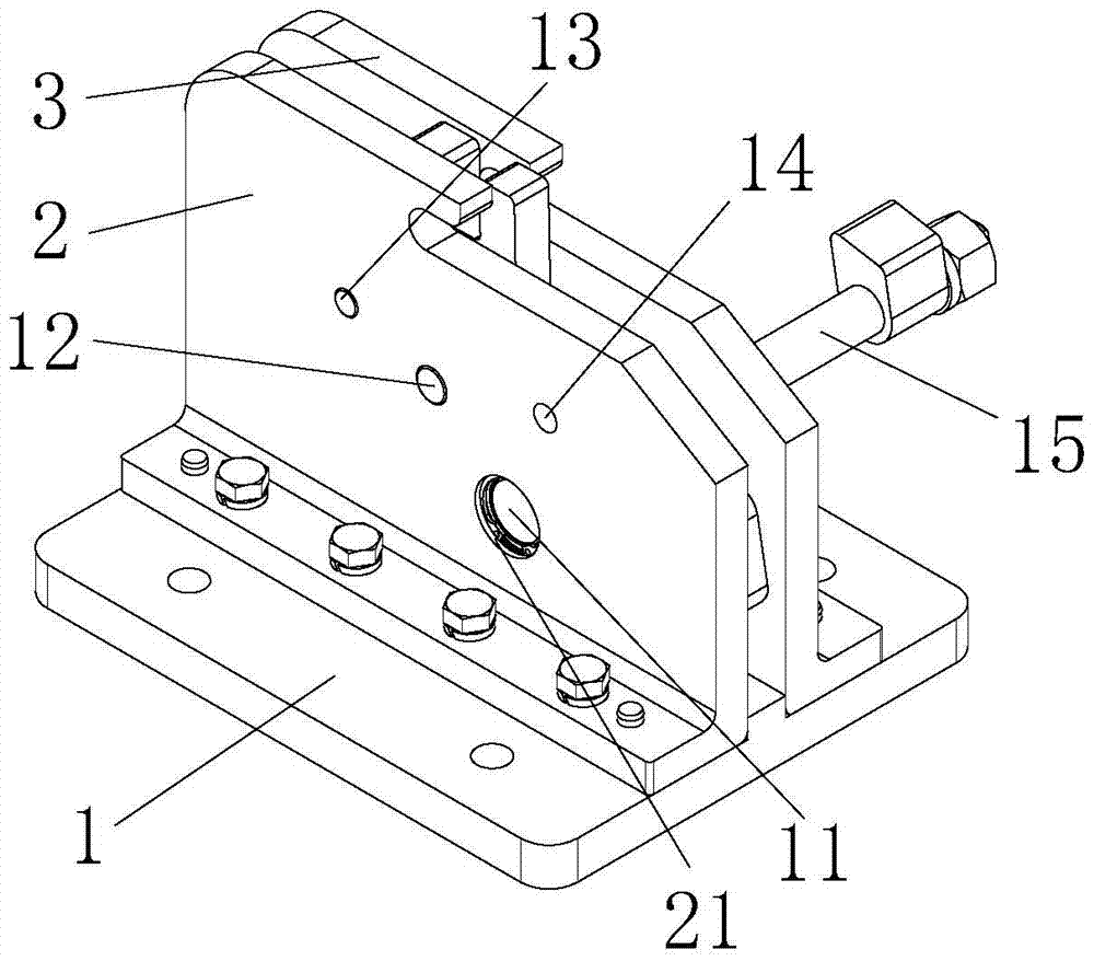
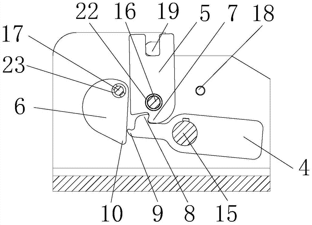
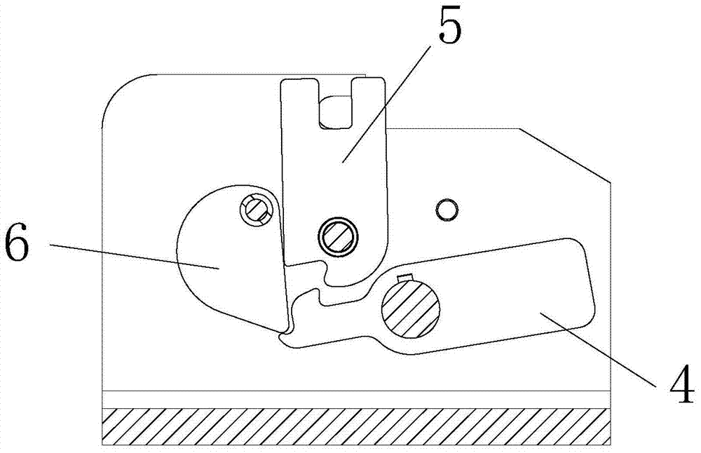
[0017] Embodiments of the invention: as figure 1 and figure 2 As shown, a self-locking mechanical lock relying on gravity includes a base 1, a housing A2, a housing B3, a main lock hook 4, a lock block 5 and a secondary lock hook 6, and the housing A2 and housing B3 are symmetrically arranged on the base 1, the main lock hook 4, the lock block 5 and the auxiliary lock hook 6 are installed between the housing A2 and the housing B3; the bottom of the lock block 5 is provided with a first hook 7, and one end of the main lock hook 4 is provided with a second hook. The second hook 8 and the third hook 9 are provided with a fourth hook 10 on the secondary lock hook 6 , the first hook 7 is matched with the second hook 8 , and the third hook 9 is matched with the fourth hook 10 .

[0018] Both housing A2 and housing B3 are provided with shaft holes A11, shaf...


PUM


Abstract

The invention discloses a gravity-based self-locking mechanical lock, which includes a base (1), a housing A (2), a housing B (3), a main lock hook (4), a lock block (5) and an auxiliary lock hook. (6), shell A (2) and shell B (3) are symmetrically arranged on the base (1), and the main lock hook (4), lock block (5) and auxiliary lock hook (6) are all installed on the shell Between A (2) and housing B (3); the bottom of the lock block (5) is provided with a first hook (7), and one end of the main lock hook (4) is provided with a second hook (8) and a third hook. (9), the auxiliary lock hook (6) is provided with a fourth hook (10), the first hook (7) matches the second hook (8), the third hook (9) matches the fourth hook (10) Cooperate. The invention can realize locking and unlocking within a small stroke range, has the advantages of simple structure and convenient unlocking, and greatly improves the stability of the mechanical lock.

Description

technical field [0001] The invention relates to a mechanical lock, in particular to a gravity self-locking mechanical lock. Background technique [0002] The existing self-locking mechanical locks are mainly ratchet mechanisms and their deformation forms. The disadvantages are: it is difficult to realize the locking and unlocking of the locking mechanism within a small stroke range, and the unlocking of the ratchet mechanism is difficult to achieve through a simple structure; When the mechanism is locked, it mainly relies on gear self-locking and friction self-locking. The former is often used in conjunction with springs. As the use time increases, due to the hazards of mechanical fatigue and mechanical wear, the safety and stability of the ratchet mechanism are greatly improved. decline. Contents of the invention [0003] The purpose of the present invention is to provide a self-locking mechanical lock relying on gravity, which can realize locking and unlocking within a ...

Claims


Application Information

Patent Timeline
Patent Type & Authority Patents(China)
IPC IPC(8): E05B63/02
Inventor 王凤文刘世缘马廉洁王佳陈杰谭福慧田俊超王华
Owner NORTHEASTERN UNIV LIAONING
Learn More