Clamping device for band penetration

A clamping device and belt threading technology, used in metal processing equipment, metal rolling, manufacturing tools, etc., can solve the problems of time-consuming, high noise, waste, etc., and achieve the effect of broad market prospects and huge economic benefits.

Pending Publication Date: 2018-08-24
WISDRI ENG & RES INC LTD
View PDF5 Cites 0 Cited by
  • Summary
  • Abstract
  • Description
  • Claims
  • Application Information

AI Technical Summary

Problems solved by technology

The existing strip threading method not only wastes a section of strip steel, but also is time-consuming, inefficient, noisy, and requires many tools (hammers, scissors, punchers, etc.)

Method used


Image

  • Clamping device for band penetration
  • Clamping device for band penetration
  • Clamping device for band penetration

Examples


Embodiment Construction

[0021] The present invention will be further described below with reference to the accompanying drawings and embodiments.

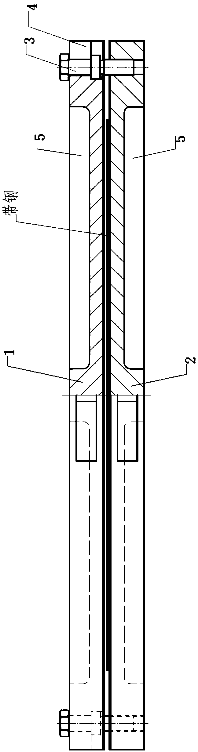
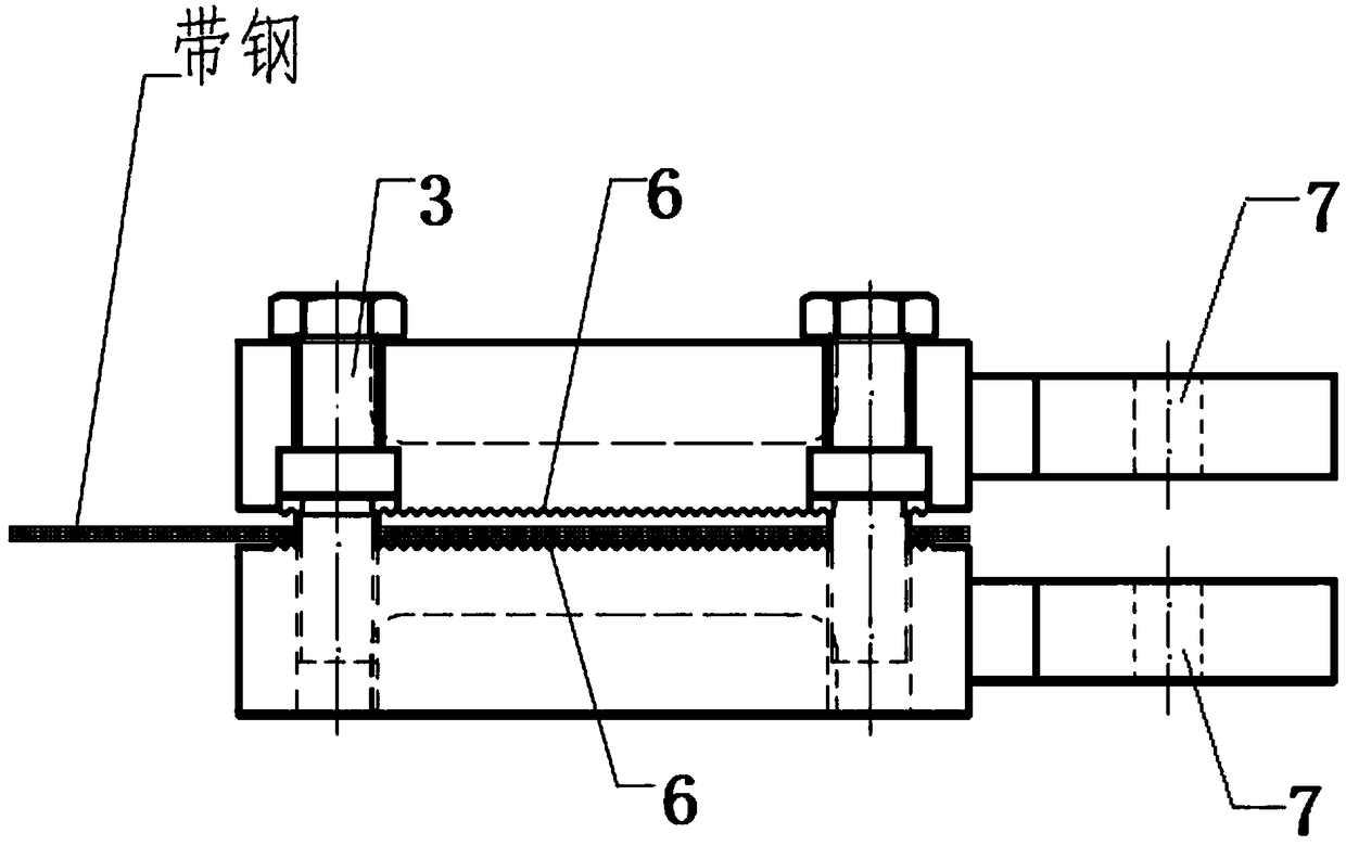
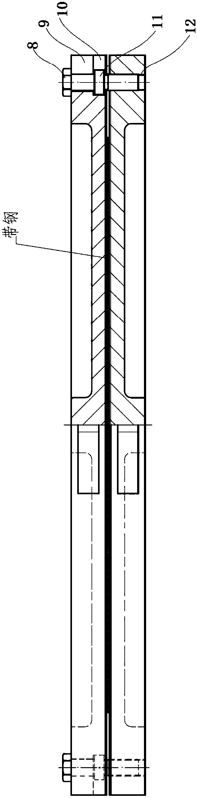
[0022] like Figure 1 to Figure 6 As shown, a belt clamping device includes an upper clamp 1, a lower clamp 2 and an adjustment bolt 3, the clamping surfaces of the upper clamp 1 and the lower clamp 2 are provided with mutually staggered anti-skid teeth 6, the upper clamp 1 and the lower clamp The front part of the splint 2 is provided with the connecting holes 7 facing each other, the left and right end surfaces of the upper splint 1 are respectively provided with two U-shaped grooves 4, front and rear, and the lower splint 2 is provided with a one-to-one correspondence with the U-shaped grooves 4. The threaded hole 12, the U-shaped groove 4 is in the shape of a second step and the upper part 9 is narrower than the lower part 10; The bolt head 8 partially covers the top surface of the upper splint 1, and the flange 11 is in clearance fit with the lower ...


PUM


Abstract

The invention relates to a clamping device for band penetration. The clamping device for band penetration comprises an upper clamping plate, a lower clamping plate and adjusting bolts. Antiskid teethare arranged on the clamping surface of the upper clamping plate. Antiskid teeth are arranged on the clamping surface of the lower clamping plate. The antiskid teeth of the upper clamping plate and the antiskid teeth of the lower clamping plate are arranged in a mutually staggered manner. A band penetration rod connecting hole is formed in the front of the upper clamping plate. A band penetrationrod connecting hole is formed in the front of the lower clamping plate. The band penetration rod connecting holes are formed in a mutually opposite manner. A front U-shaped groove and a rear U-shapedgroove are formed in each of the left end face and the right end face of the upper clamping plate. Threaded holes corresponding to the U-shaped grooves one to one are formed in the lower clamping plate. Each U-shaped groove is in the shape of a two-step stair, and the upper step part of the U-shaped groove is narrower than the corresponding lower step part. Each adjusting bolt is provided with a bolt head on the upper part and a convex edge in the middle, and the lower part of the adjusting bolt is matched with the corresponding threaded hole. The bolt head part of each adjusting bolt covers the top surface of the upper clamping plate. The convex edge of each adjusting bolt is in clearance fit with the lower step part of the corresponding U-shaped groove. When each bolt head is tightened,the bolt head drives the upper clamping plate to move downwards to clamp band steel, and when each bolt head is turned reversely, the corresponding convex edge drives the upper clamping plate to moveupwards so as to release the band steel. The clamping device for band penetration is high in efficiency, higher in yield, free of noise, low in cost and convenient to use.

Description

technical field [0001] The invention belongs to the field of cold rolling equipment, in particular to a belt threading and clamping device. Background technique [0002] In cold-rolled strip mills, continuous horizontal furnace annealing lines and galvanizing lines require strip threading rods to complete strip threading work—a handful of strip heads are folded, chamfered and placed in the middle of the strip heads Punch a round hole, then use bolts to connect the strip steel to the strip rod, and then drive the strip rod and the strip to run forward through the roller drive to complete the strip work. The existing belt threading method not only wastes a section of strip steel, but also is time-consuming, inefficient, noisy, and requires many tools (hammers, scissors, punches, etc.). SUMMARY OF THE INVENTION [0003] The purpose of the present invention is to provide a belt threading and clamping device, which has high efficiency, improves the yield, does not generate noi...

Claims


Application Information

Patent Timeline
IPC IPC(8): B21B39/00
CPCB21B39/00
Inventor 张齐兵
Owner WISDRI ENG & RES INC LTD
Why Eureka
Try Eureka