Cutter body end surface positioning groove machining tooling

A positioning groove and cutter body technology, which is applied in the direction of metal processing equipment, manufacturing tools, grinding workpiece supports, etc., can solve the problems that affect the processing quality and the position height of the grinding wheel cannot meet the processing requirements, so as to achieve convenient grinding wheel processing, easy processing, The effect of reducing the positioning height

Inactive Publication Date: 2015-03-11
CHONGQING SANGUI MACHINERY MFG
View PDF0 Cites 0 Cited by
  • Summary
  • Abstract
  • Description
  • Claims
  • Application Information

AI Technical Summary

Problems solved by technology

[0002] A tool is a tool used for cutting in mechanical manufacturing. The tool includes a clamping part and a working part. Usually, the clamping part and the working part of the tool are set on the cutter body through a key connection. Therefore, grinding is required on the cutter body. Manufacture a symmetrical positioning keyway. The grinding positioning keyway is usually positioned with a positioning disc on a tool grinder. The tool grinding machine has a high work surface and a long cutter body. The cutter body is positioned on the surface of the positioning disc. The top of the cutter body protrudes higher. There will be a problem that the position height of the grinding wheel cannot meet the processing requirements, which will affect the processing quality

Method used


Image

  • Cutter body end surface positioning groove machining tooling
  • Cutter body end surface positioning groove machining tooling

Examples


Embodiment Construction

[0012] The present invention will be described in further detail below by means of specific embodiments:

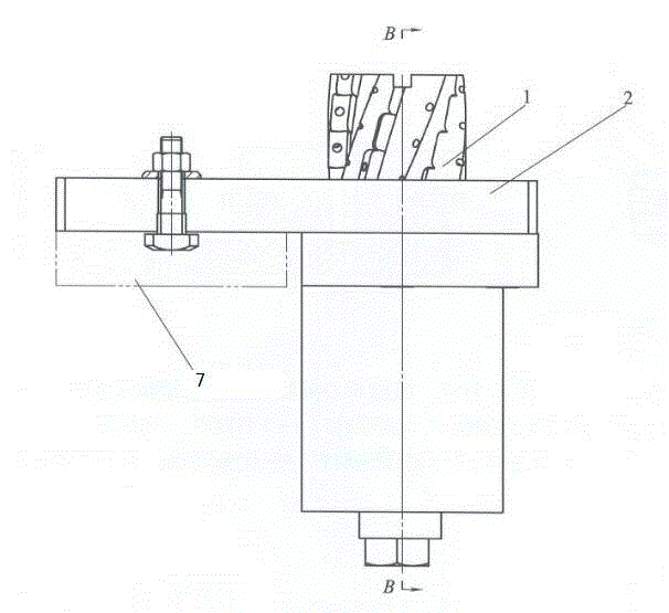
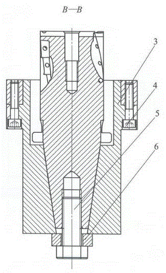
[0013] The reference signs in the accompanying drawings of the description include: cutter body 1, positioning plate 2, counterbore sleeve 3, fastening screw 4, fastening bolt 5, gasket 6, machine tool table 7.

[0014] as attached figure 1 and 2 As shown: the lower surface of one side of the positioning plate 2 is disassembled and connected to the machine tool table through bolts, and a through hole is opened on the other side of the positioning plate 2, and the counterbore sleeve 3 is axially positioned in the through hole. The upper surface of the hole sleeve 3 is on the same plane as the upper surface of the positioning plate 2 .

[0015] The counterbore sleeve 3 is provided with an upper circular hole and a lower taper hole whose taper matches the outer taper of the cutter along its axial direction. The taper of the lower taper hole is 7:20. The outside gradually ...


PUM


Abstract

The invention discloses a cutter body end surface positioning groove machining tooling to reduce the positioning height during cutter body machining to be matched with the height of a grinding wheel and improve the positioning key groove machining quality. The cutter body end surface positioning groove machining tooling comprises a positioning plate which can be detachably connected with a machine tool table; a through hole is formed in the positioning plate; a countersink sleeve is axially positioned inside the through hole; an upper circular hole and a lower taper hole with the taper being matched with the exterior taper of a cutter body are formed in the countersink sleeve along the axial direction; the hole diameter of the lower taper hole is gradually reduced from the interior of the countersink sleeve to the exterior; the upper circular hole is communicated with the lower taper hole; the hole diameter of the upper circular hole is larger than the internal hole diameter of the lower taper hole; the upper circular hole and the lower taper hole commonly form into a cutter body positioning hole; an external hole of the lower taper hole is provided with a fastening bolt which can position the cutter body end surface. According to the cutter body end surface positioning groove machining tooling, the countersink sleeve is designed, the cutter body is positioned inside the upper circular hole and the lower taper hole, and accordingly, the integral positioning height of the cutter body can be reduced to be matched with the height of the grinding wheel, grinding wheel machining is convenient, and the quality of the grinding wheel mill groove can be improved.

Description

technical field [0001] The invention specifically relates to a processing tool for positioning grooves on the end face of a cutter body. Background technique [0002] A tool is a tool used for cutting in mechanical manufacturing. The tool includes a clamping part and a working part. Usually, the clamping part and the working part of the tool are set on the cutter body through a key connection. Therefore, grinding is required on the cutter body. Manufacture a symmetrical positioning keyway. The grinding positioning keyway is usually positioned with a positioning disc on a tool grinder. The tool grinding machine has a high work surface and a long cutter body. The cutter body is positioned on the surface of the positioning disc. The top of the cutter body protrudes higher. There will be a problem that the position height of the grinding wheel cannot meet the processing requirements, which will affect the processing quality. Contents of the invention [0003] The invention pr...

Claims


Application Information

Patent Timeline
Patent Type & Authority Applications(China)
IPC IPC(8): B24B19/02B24B41/06
CPCB24B19/02B24B41/06
Inventor 高学文
Owner CHONGQING SANGUI MACHINERY MFG
Why Eureka
Try Eureka