Path Disturbance Suppression Method Based on Ionospheric Propagation Characteristics
A technology of phase disturbance and propagation characteristics, applied to radio wave measurement systems, instruments, etc., can solve problems such as failure and limited suppression, and achieve the effect of wide application conditions, obvious suppression, and suppression of phase disturbance
- Summary
- Abstract
- Description
- Claims
- Application Information
AI Technical Summary
Problems solved by technology
Method used
Image
Examples
specific Embodiment approach 1
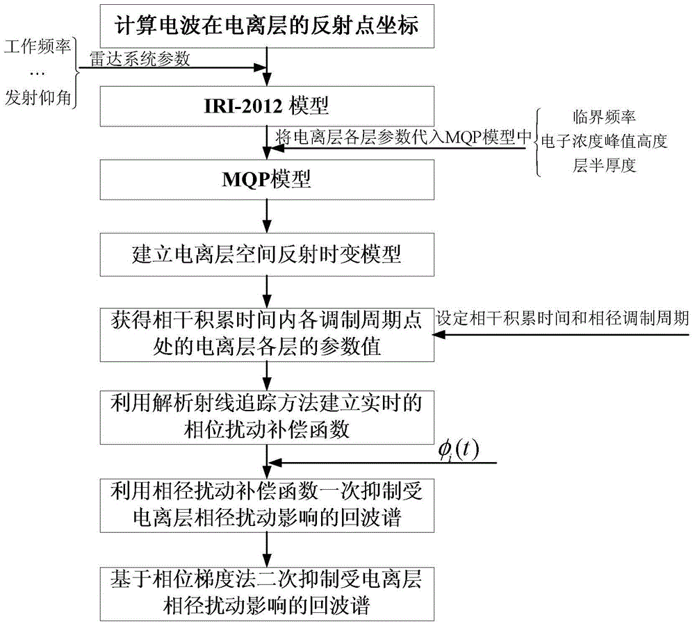
[0024] Embodiment 1: A method for suppressing phase disturbance based on ionospheric propagation characteristics described in this embodiment includes the following steps:
[0025] Step 1, calculating the coordinates of the reflection point of the radio wave in the ionosphere;
[0026] Step 2, establishment of ionospheric space reflection time-varying model;
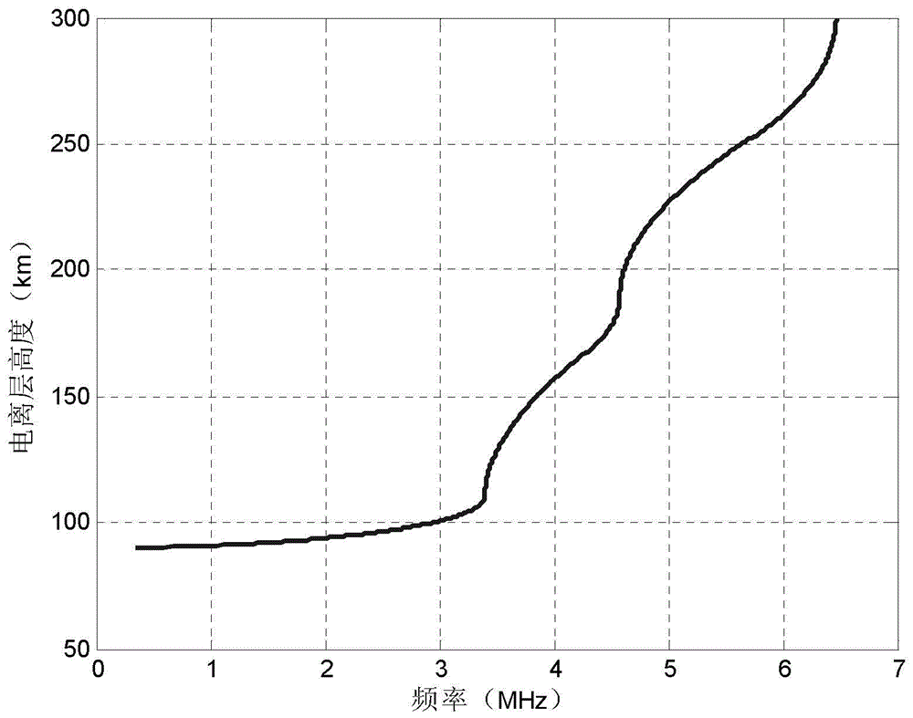
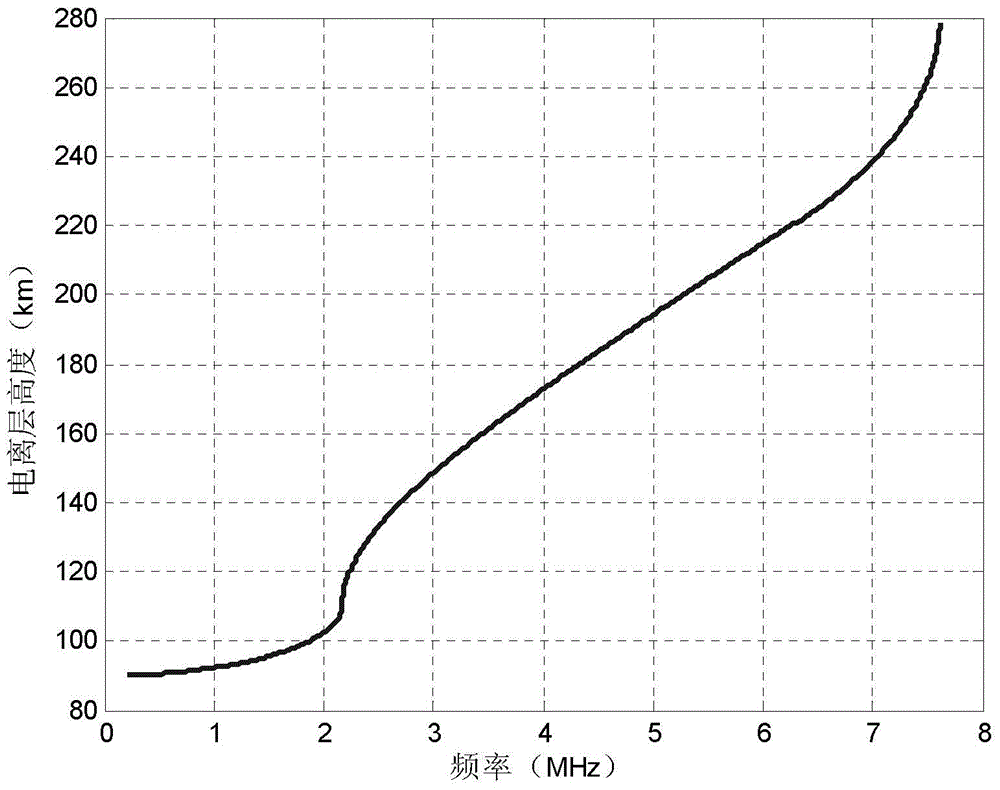
[0027] In order to solve the problem of low accuracy of the IRI model and the inconvenience of obtaining parameters from the MQP model, a time-varying ionospheric reflection model was obtained by hybrid modeling of the International Reference Ionosphere Model (IRI-2012) and the Multi-Quasi-Parabolic Model (MQP), That is, the real-time changing parameter critical frequency f of each layer of the ionosphere in the reflection area is calculated by the IRI-2012 model m , electron concentration peak height r m and layer half-thickness y m ) into the MQP model to establish a time-varying model of ionospheric space reflectio...
specific Embodiment approach 2
[0091] Specific embodiment two: the difference between this embodiment and specific embodiment one is: the calculation process of the reflection point coordinates described in step one is:
[0092] According to the coordinates of the transmitter and the center coordinates of the detection area, the coordinates of the reflection point are calculated by the following formula:
[0093]
[0094] Among them, N lon and N lat are the longitude and latitude of the reflection point, T lon and T lat are the latitude and longitude of the transmitter respectively, R lon and R lat are the coordinates of the center of the detection area.
specific Embodiment approach 3
[0095] Specific implementation mode three: the difference between this implementation mode and specific implementation mode one or two is: the establishment process of the reflection time-varying model described in step two is:
[0096] According to the specific system layout and parameter requirements of the sky-wave radar, input the working time, working frequency, launch elevation angle, launch azimuth angle, and reflection point coordinates into the IRI-2012 model, and obtain the critical frequency of each layer of the ionosphere through the IRI-2012 model f m , electron concentration peak height r m and layer half-thickness y m Finally, it is passed to the MQP model, where m is the number of layers of the ionosphere, so as to complete the hybrid modeling of MQP and IRI-2012, and obtain the ionospheric spatial reflection time-varying model.
PUM
 Abstract
Description
Claims
Application Information
 - R&D
- Intellectual Property
- Life Sciences
- Materials
- Tech Scout
- Unparalleled Data Quality
- Higher Quality Content
- 60% Fewer Hallucinations
Browse by: Latest US Patents, China's latest patents, Technical Efficacy Thesaurus, Application Domain, Technology Topic, Popular Technical Reports.
© 2025 PatSnap. All rights reserved.Legal|Privacy policy|Modern Slavery Act Transparency Statement|Sitemap|About US| Contact US: help@patsnap.com


