Single-screw boosting water injection pump

A single-screw pump and injection pump technology, applied in the fields of production fluids, wellbore/well components, earth-moving drilling, etc., can solve the problems of unstable operation, frequent maintenance, high energy consumption, etc. The effect of injecting benefits and increasing the amount of water injection

Inactive Publication Date: 2015-03-04
张成功
View PDF8 Cites 1 Cited by
  • Summary
  • Abstract
  • Description
  • Claims
  • Application Information

AI Technical Summary

Problems solved by technology

For example, when the ground plunger pump is pressurized, the pressure fluctuates greatly, the operation is not stable, the seal is damaged quickly, the management work is difficult, the maintenance is frequent, the labor intensity of the workers is high, and the pressurized water injection often stops, resulting in pressure fluctuations in the water injection well, causing expansion and contraction of the tools in the well and formation Sand spewing, shortening the water injection cycle, and the use of ground plunger pumps for pressurized water injection also occupies the well site; due to the small injection volume and high pressure of single well pressurized water injection, if the centrifugal pump is used for pressurized water injection, there will be low efficiency and energy consumption It is a big problem, and the centrifugal pump rotates at high speed, and the sealing requirements are high under the condition of high pump inlet pressure. The existing sealing device cannot meet the requirements of using water injection pipe network to pressurize to low-permeability water injection wells
Another example is the Chinese patent 201010114436.5 "pressurized water injection device", which requires a ground pumping unit for pressurized water injection, the ground equipment is huge, the cost is high, and the efficiency is low

Method used


Image

  • Single-screw boosting water injection pump

Examples


Embodiment Construction

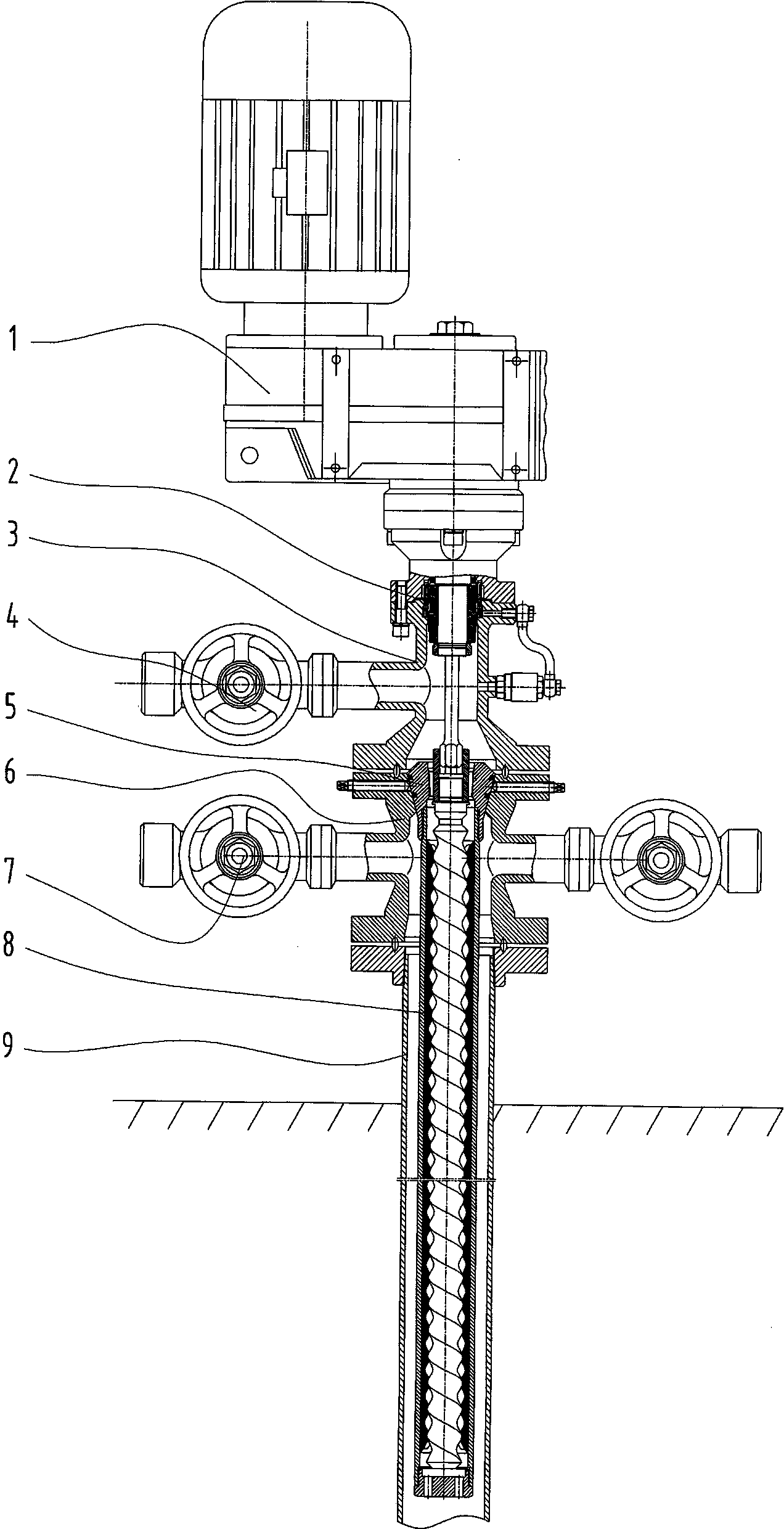
[0007] Depend on figure 1 It can be seen that the embodiment of the present invention includes a rotary power device 1, a mechanical seal device 2, a tee 3, a water inlet valve 4, a hanger 5, a cross 6, a casing valve 7, a single screw pump 8, a casing 9, and four The lower part of the pass 6 is connected to the upper part of the casing 9, the hanger 5 is seated on the upper end hole of the cross 6, the contact between the hanger 5 and the cross 6 is kept sealed, and the single screw pump is connected under the hanger 5 8, the stator of the single screw pump 8 is in the casing 9, the casing valve 7 is installed on the side port of the four-way 6, two casing valves 7 are generally symmetrically installed, and the three-way 3 is installed on the upper end of the four-way 6, The water inlet valve 4 is installed on the side port of the tee 3, and the mechanical seal device 2 is installed in the upper part of the tee 3. The mechanical seal device 2 is a series mechanical seal devic...


PUM


Abstract

The invention discloses a single-screw boosting water injection pump which is characterized in that the lower part of a four-way joint is connected with the upper part of a sleeve pipe; a suspender is arranged on the upper end hole of the four-way joint; the part of contact between the suspender and the four-way joint is kept sealed; a stator of a single-screw pump is connected to the lower part of the suspender and arranged in the sleeve pipe; a sleeve pipe valve is mounted on the side opening of the four-way joint; a tee joint is mounted on the upper end surface of the four-way joint; a water inlet valve is mounted on the side opening of the tee joint; a mechanical seal device is mounted in the upper part of the tee joint; a rotary power device is mounted at the upper end of the tee joint; a central shaft of the rotary power device penetrates through the mechanical seal device to be connected with a rotor of the single-screw pump and can drive the rotor of the single-screw pump to rotate. The single-screw boosting water injection pump is stable in running, free of pulsation, low in fault rate, reliable to seal and long in service life; the water injection amount can be increased and the water injection cycle can be prolonged; the single-screw boosting water injection pump is mounted in a well with boosting water injection requirements, does not take up ground space and has remarkable economic benefits.

Description

technical field [0001] The invention relates to equipment for water injection in oil fields, which is a single-screw booster water injection pump. Background technique [0002] Individual water injection wells require high-pressure water to be injected into the formation. Various oilfields have adopted a variety of pressurization equipment, mainly including surface plunger pumps and centrifugal pumps. These pumps are used to boost the pressure on the existing water injection pipe network and then inject high-pressure water into the formation. In the water injection wells in China, these pressurization equipment all have the problem of high failure rate. For example, when the surface plunger pump is pressurized, the pressure fluctuates greatly, the operation is not stable, the seal is damaged quickly, the management work is difficult, the maintenance is frequent, the labor intensity of the workers is high, and the pressurized water injection often stops, causing pressure fluc...

Claims


Application Information

Patent Timeline
Patent Type & Authority Applications(China)
IPC IPC(8): E21B43/20
CPCE21B43/20
Inventor 马小石刘业文吴晖周亮崔殿孙志勇高红娟王颖李昌顺
Owner 张成功
Why Eureka
Try Eureka