
Pipe tool transportation mechanical arm

A technology of manipulator and pipe tool, applied in the direction of drill pipe, casing, drilling equipment, etc., can solve the problems of pipe tool pushing off and dumping, complicated programming and control, and damage to the thread of drilling tool, so as to achieve the synchronization of extension speed and displacement. , simple programming and control, simple maintenance effect

Active Publication Date: 2015-03-04
SICHUAN HONGHUA PETROLEUM EQUIP
View PDF6 Cites 25 Cited by
  • Summary
  • Abstract
  • Description
  • Claims
  • Application Information

AI Technical Summary

Problems solved by technology

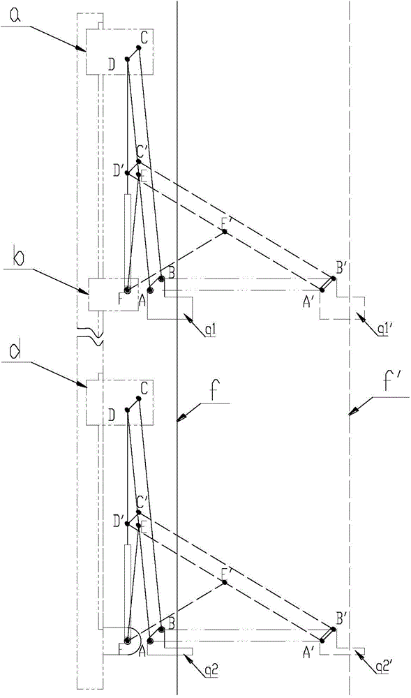
[0005] There are following deficiencies in above-mentioned two kinds of structural manipulators: 1, Figure 17 The structure of the upper and lower mechanical arms in the shown mechanical arm structure is exactly the same, which seems simple, but in the process of retracting and extending the mechanical arm, the starting position of point A of the connecting rod a is not on the same straight line as the ending position A', Its trajectory AA' is arc-shaped, which causes the start position and end position of the clamp to be different from the same height, which also leads to inconsistent heights from the table during the extension and retraction of the pipe.
Furthermore, programming and control are still very complicated, and debugging is difficult
3. In addition, when the above-mentioned two kinds of pipe rowing machines are on and off for a single pipe, the weight of the entire pipe will act on the drill string below, which may easily cause damage to the thread of the drill
However, the manipulator clamp with the above structure has a small range of clamping pipes (3in~6 5 / 8in), and there are potential safety hazards; Appears at the edge of the jaw (eg Figure 20 ), affecting the clamping effect and the life of the jaws; and it is impossible to judge whether the pipe has entered the clamping center of the manipulator when grabbing the pipe. If it has not entered, the pliers will start to close, and the pipe will be pushed instead. away from dumping

Method used


Image

  • Pipe tool transportation mechanical arm
  • Pipe tool transportation mechanical arm
  • Pipe tool transportation mechanical arm

Examples


Embodiment 1

[0052] Figure 1 to Figure 4 The main beam 6 of the pipe arrangement machine shown in is the installation carrier of the pipe transfer manipulator in this embodiment. The upper and lower ends of the main beam 6 of the pipe arrangement machine are respectively hinged on the upper and lower traveling devices, which can realize the overall movement and rotation of the entire pipe transfer manipulator.

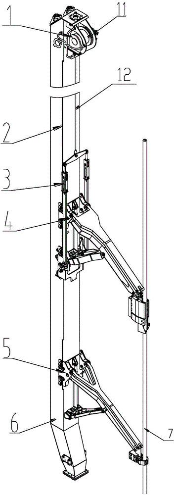
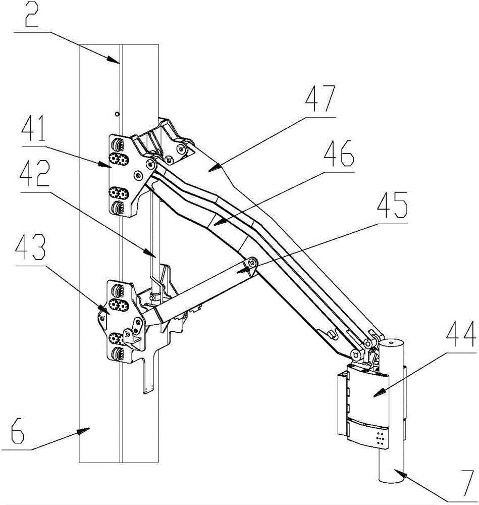
[0053] The pipe transfer manipulator of this embodiment is as follows: figure 1 As shown, it includes a lifting device 1, a guide rail 2, a counterweight device 3, an upper manipulator 4 and a lower manipulator 5. The guide rail 2 is fixed on both sides ahead of the main beam 6 of the pipe arrangement machine, and the upper manipulator 4 and the lower manipulator 5 are installed on the guide rail 2 by rollers, and the guide rail 2 provides moving lines for the sliding of the upper manipulator 4 and the lower manipulator 5. The lifting device 1 includes a winch 11 and a wire rop...


PUM


Abstract

The invention discloses a pipe tool transportation mechanical arm, and belongs to the technical field of petroleum drill and exploitation equipment machinery. The pipe tool transportation mechanical arm comprises a guide rail, an upper mechanical arm and a lower mechanical arm, wherein the guide rail is installed on a girder of a tube draw bench, and the upper mechanical arm and the lower mechanical arm are installed on the guide rail. According to the pipe tool transportation mechanical arm, clamping pincers and righting pincers keep moving along the horizontal direction from beginning to end, displacement of a stand pipe is kept changeless in the vertical direction before and after a person grasps the stand pipe, and the person does not need to additionally regulate the vertical height of the stand pipe during the transportation process of the stand pipe. Furthermore, due to the fact that the upper mechanical arm and the lower mechanical arm adopt the same working principle, the person only needs to use the same control curve in control software for a first telescopic oil cylinder and a second telescopic oil cylinder under the condition that the first telescopic oil cylinder and the second telescopic oil cylinder are of the same specification, and then the purpose of respectively keeping stretching velocity and displacement of the upper mechanical arm and the lower mechanical arm synchronous is achieved. A control system of the pipe tool transportation mechanical arm is simple in programming and control, easy to implement and simple to debug, and therefore the pipe tool transportation mechanical arm is low in cost and simple to maintain.

Description

technical field [0001] The invention relates to a pipe transfer manipulator, in particular to a new pipe transfer manipulator used for discharging vertical drill pipes and drill collars on an offshore oil drilling platform, and belongs to the technical field of petroleum drilling equipment machinery. Background technique [0002] The pipe racking machine is a transportation tool in the pipe processing system of an oil drilling rig. In order to perform fast drilling operations in drilling operations, it is usually necessary to connect multiple drill pipes, drill collars and casings in advance to form roots and store them inside the derrick fingerboard. The pipe rowing machine is a manipulator that clamps and transports the vertical root during the process of the vertical root being grasped, transported, removed and connected to the drill string. [0003] Due to the limitation of the working space, the pipe arrangement machine on the land drilling rig is basically operated by...

Claims


Application Information

Patent Timeline
Patent Type & Authority Applications(China)
IPC IPC(8): E21B19/14
CPCE21B19/14
Inventor 于芳魏双会常健高杭何波
Owner SICHUAN HONGHUA PETROLEUM EQUIP
Learn More