
A pressure-adjustable inflation and deflation method

A technology of inflating and deflating and adjusting the pressure, applied in tire inflation valve, tire parts, transportation and packaging, etc., can solve the problems of low efficiency, inconvenient operation, inability to deflate, etc. Improve the effect of construction

Active Publication Date: 2017-02-22
柳工无锡路面机械有限公司
View PDF7 Cites 0 Cited by
  • Summary
  • Abstract
  • Description
  • Claims
  • Application Information

AI Technical Summary

Problems solved by technology

[0003] There are two types of inflation and deflation systems for conventional tire rollers: one is to use an external air pump to inflate the tires, and the deflation generally depends on manually pushing the tire valve core, which is inefficient and not easy to operate; the other One is to use the air booster pump of the engine to inflate the tires, but the construction conditions require that the tire rollers need to work with different tire pressures according to different working conditions, but this method can only work in one direction, that is, only It can be inflated but not deflated. Even if you want to deflate, you must remove the inflation pipe and deflate manually. Therefore, this method cannot be applied to occasions that require frequent inflation and deflation of tires to adjust tire pressure; therefore, Chinese patent ZL201110196331.3 discloses "a control combination valve for vehicle tire inflation and deflation system". This structure can use a set of equipment to realize inflation and deflation. Its structure is complex, and when it is switched between charging and discharging, it is also necessary to change the connection of the gas circuit, which affects the efficiency of charging and discharging

Method used


Image

  • A pressure-adjustable inflation and deflation method

Examples


Embodiment Construction

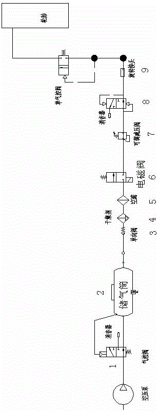
[0019] see figure 1 , the present invention relates to an adjustable pressure filling and deflation loop system, said system includes an air control valve 1, an air storage tank 2, a one-way valve 3, an air filter 5, a solenoid valve 6, an adjustable reducing Pressure valve 7, double air control valve 8, rotary joint 9 and single air control valve 10, the air control valve 1 is connected with the air outlet end of the air pump, and the single air control valve 10 is connected with the air nozzle of the tire;

[0020] A pressure-adjustable inflation and deflation method of the present invention:

[0021] When inflated:

[0022] Step 1.1: Open the solenoid valve 6, adjust the adjustable pressure reducing valve 7 to the required pressure value (the pressure value at this time is greater than the air pressure in the tire), the gas introduced by the air pump passes through the air control valve 1, the air storage tank 2, the single Output the gas corresponding to the pressure of ...


PUM


Abstract

The invention relates to an adjustable pressure type inflation and deflation loop system and an inflation and deflation method thereof. The system comprises a pneumatic control valve (1), a gas storage cylinder (2), a one-way valve (3), an air filter (5), a solenoid valve (6), an adjustable reducing valve (7), a double pneumatic control valve (8), a rotary joint (9) and a single pneumatic control valve (10) which are sequentially connected with one another, wherein the pneumatic control valve (1) is communicated with the air outlet end of an air pump; and the single pneumatic control valve (10) is communicated with an air faucet of a tire. According to the adjustable pressure type inflation and deflation loop system and the inflation and deflation method thereof, disclosed by the invention, the structure is simple, and the inflation and the deflation can be realized by adopting a same connection manner and a same pipeline.

Description

technical field [0001] The invention relates to an inflation and deflation circuit and an inflation and deflation method thereof, in particular to an adjustable pressure inflation and deflation method for tires of wheeled construction machinery such as tire road rollers and the inflation and deflation method thereof, belonging to construction machinery The technical field of inflation and deflation of tires. Background technique [0002] At present, according to the construction requirements, when the tire roller is working, it is necessary to adjust the tire pressure according to different working conditions. To adjust the tire pressure, the gas in the tire needs to be inflated and deflated; [0003] There are two types of inflation and deflation systems for conventional tire rollers: one is to use an external air pump to inflate the tires, and the deflation generally depends on manually pushing the tire valve core, which is inefficient and not easy to operate; the other O...

Claims


Application Information

Patent Timeline
Patent Type & Authority Patents(China)
IPC IPC(8): B60C29/00
Inventor 黄北京宋鹏飞黄晓吴晓健孙甜甜鞠鹏
Owner 柳工无锡路面机械有限公司
Learn More