Fixing frame for polishing of compressor spindle
A compressor and fixing frame technology, applied in the direction of grinding workpiece supports, etc., can solve the problem of incomplete grinding of the rotating shaft, and achieve the effect of improving grinding efficiency and avoiding safety accidents.
- Summary
- Abstract
- Description
- Claims
- Application Information
AI Technical Summary
Problems solved by technology
Method used
Image
Examples
Embodiment 1
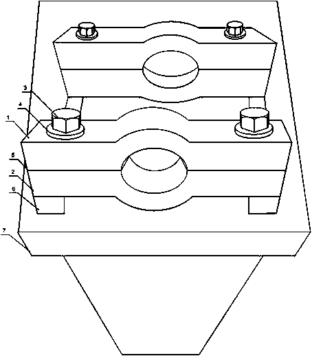
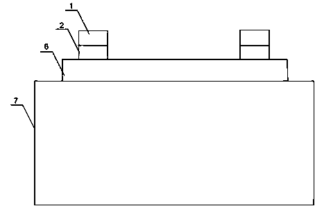
[0020] Such as figure 1 As shown, this embodiment includes a bracket 7, a slide 6 and a fixing mechanism. The slide 6 is mounted on the bracket 7. The fixing mechanism includes an upper chuck 1 and a lower chuck 2. The upper chuck 1 is slidably arranged on the slide 6, the upper chuck 1 is provided with a semicircular arc concave surface A, the lower chuck 2 is provided with a semicircular arc concave surface B, the semicircular arc concave surface A and the semicircular arc concave surface B form a circular cavity, the upper chuck 1 Connect with the lower chuck 2 bolts. Adjust the bolt 3 between the upper chuck 1 and the lower chuck 2 so that the ends of the shaft are placed in the arc concave surface A, and then adjust the distance between the two by moving the two fixing mechanisms on the slide. The shafts of different lengths can be clamped and fixed. The arc concave surface A and the semi-circular arc concave surface B form a circular cavity for the ends of the shaft to pa...
Embodiment 2
[0023] Such as figure 1 As shown, on the basis of Embodiment 1, this embodiment further includes an elastic gasket 5 provided between the upper chuck 1 and the lower chuck 2. The upper chuck 1 and the lower chuck 2 will stick to each other when they are fixed. The force generated by the grinder when it comes into contact with the rotating shaft will cause the upper chuck 1, the lower chuck 2 and the end of the rotating shaft to collide with each other. Certain damage; the elastic gasket 5 provided can protect the end of the shaft, reduce the impact on the end of the shaft, and prevent it from being damaged.
Embodiment 3
[0025] Such as figure 1 As shown, in this embodiment on the basis of embodiment 1, the bottom of the lower chuck 1 is also symmetrically provided with two shock-proof feet, which can buffer most of the force, avoid the vibration of the fixing mechanism during polishing, and ensure the polishing Accuracy: A ring gasket 4 is provided between the bolt 3 and the upper chuck 1. As the position of the shaft needs to be adjusted from time to time during grinding, the adjustment of the bolt 3 is more frequent. Long-term use will affect the bolt 3. If the thread breaks or the head of the bolt 3 separates from the screw, the provided ring gasket 4 can strengthen the connection between the bolt 3 and the upper chuck 1, and extend the service life of the bolt 3.
PUM
 Abstract
Description
Claims
Application Information
 - R&D
- Intellectual Property
- Life Sciences
- Materials
- Tech Scout
- Unparalleled Data Quality
- Higher Quality Content
- 60% Fewer Hallucinations
Browse by: Latest US Patents, China's latest patents, Technical Efficacy Thesaurus, Application Domain, Technology Topic, Popular Technical Reports.
© 2025 PatSnap. All rights reserved.Legal|Privacy policy|Modern Slavery Act Transparency Statement|Sitemap|About US| Contact US: help@patsnap.com


