Rotomolding molds and strategies for using rotational molds
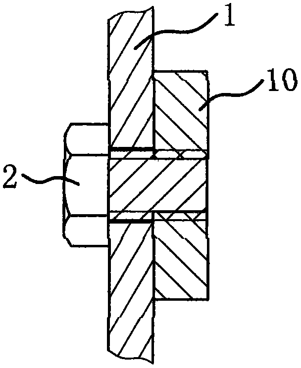
A rotomolding mold and strategy technology, applied in coating and other directions, can solve the problems of mold removal time affecting product shrinkage, reducing product qualification rate, complex rotomolding molds, etc., to improve speed, reduce labor costs, and improve the qualification rate. Effect
- Summary
- Abstract
- Description
- Claims
- Application Information
AI Technical Summary
Problems solved by technology
Method used
Image
Examples
Embodiment 1
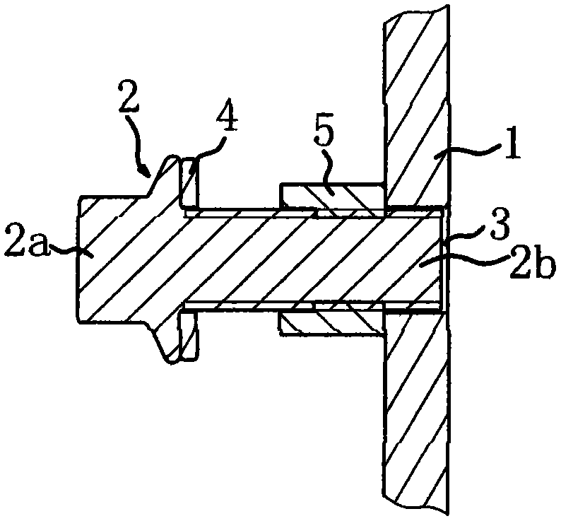
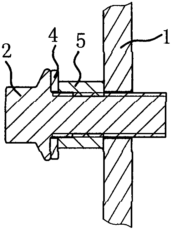
[0026] Such as Figure 2 to Figure 4 As shown, the rotomolding mold includes a template 1, and the template 1 surrounds a mold cavity. This rotomolding mold is suitable for producing products with inserts 10. The rotomolding mold also includes bolts 2 for fixing the inserts 10. There are bolt holes 3 on the template 1. The head 2a of the bolt 2 is located outside the template 1. The bolts The screw part 2b of 2 can penetrate into the mold cavity from the bolt hole 3. A nut 5 is threaded on the screw part 2b of the bolt 2, and the nut 5 is located outside the formwork 1, and the nut 5 and the formwork 1 are fixedly connected by welding; the head 2a of the bolt 2 can abut against the nut 5.
[0027] A washer 4 is provided between the head 2 a of the bolt 2 and the nut 5 , and the washer 4 is sheathed on the screw portion 2 b of the bolt 2 .
[0028] The usage strategy of the rotomolding mold includes a method of installing the insert 10 and a method of dismounting the insert 1...
Embodiment 2
[0032] Such as Figure 5 to Figure 8 As shown, the rotomolding mold includes a template 1 and a bolt 2, the template 1 is provided with a bolt hole 3, the head 2a of the bolt 2 is located outside the template 1, and the screw part 2b of the bolt 2 can pass through the bolt hole 3; the bolt 2 The screw part 2b is sheathed with an outer sleeve 6 and threaded with a nut 5 , and both the nut 5 and the outer sleeve 6 are located on the outside of the formwork 1 . The outer sleeve 6 is a hexagonal tube, and the nut 5 is located in the outer sleeve 6, thus avoiding the circumferential rotation between the nut 5 and the outer sleeve 6, and the nut 5 and the outer sleeve 6 are then fixedly connected by screws 7 or welded. One end of the outer casing 6 is fixedly connected with the template 1 by welding, and the head 2 a of the bolt 2 can abut against the other end surface of the outer casing 6 .
[0033] The screw portion 2b of the bolt 2 is provided with an open retaining ring 8, and...
PUM
 Abstract
Description
Claims
Application Information
 - R&D
- Intellectual Property
- Life Sciences
- Materials
- Tech Scout
- Unparalleled Data Quality
- Higher Quality Content
- 60% Fewer Hallucinations
Browse by: Latest US Patents, China's latest patents, Technical Efficacy Thesaurus, Application Domain, Technology Topic, Popular Technical Reports.
© 2025 PatSnap. All rights reserved.Legal|Privacy policy|Modern Slavery Act Transparency Statement|Sitemap|About US| Contact US: help@patsnap.com


