Flow-controllable continuous sandblasting machine

A technology of sandblasting machine and flow rate, applied in the field of sandblasting machine, can solve the problems of clogging of pipelines and nozzles, and achieve the effect of accurately adjusting the injection volume

Inactive Publication Date: 2015-03-04
郭晓军
View PDF6 Cites 5 Cited by
  • Summary
  • Abstract
  • Description
  • Claims
  • Application Information

AI Technical Summary

Problems solved by technology

[0006] In order to overcome the deficiencies of the prior art, the present invention provides a continuous sandblasting machine with controllable flow rate, which is suitable for spraying easily agglomerated substances such as baking soda. The sandblasting machine uses dry compressed air as the power source, and utilizes Venturi The principle is to transport baking soda powder, which solves the problem of pipeline and nozzle blockage caused by baking soda agglomeration; at the same time, the lifting position of the center tube is cleverly adjusted to realize continuous, uniform and precisely adjustable flow of baking soda spray Operation

Method used


Image

  • Flow-controllable continuous sandblasting machine
  • Flow-controllable continuous sandblasting machine
  • Flow-controllable continuous sandblasting machine

Examples


Embodiment Construction

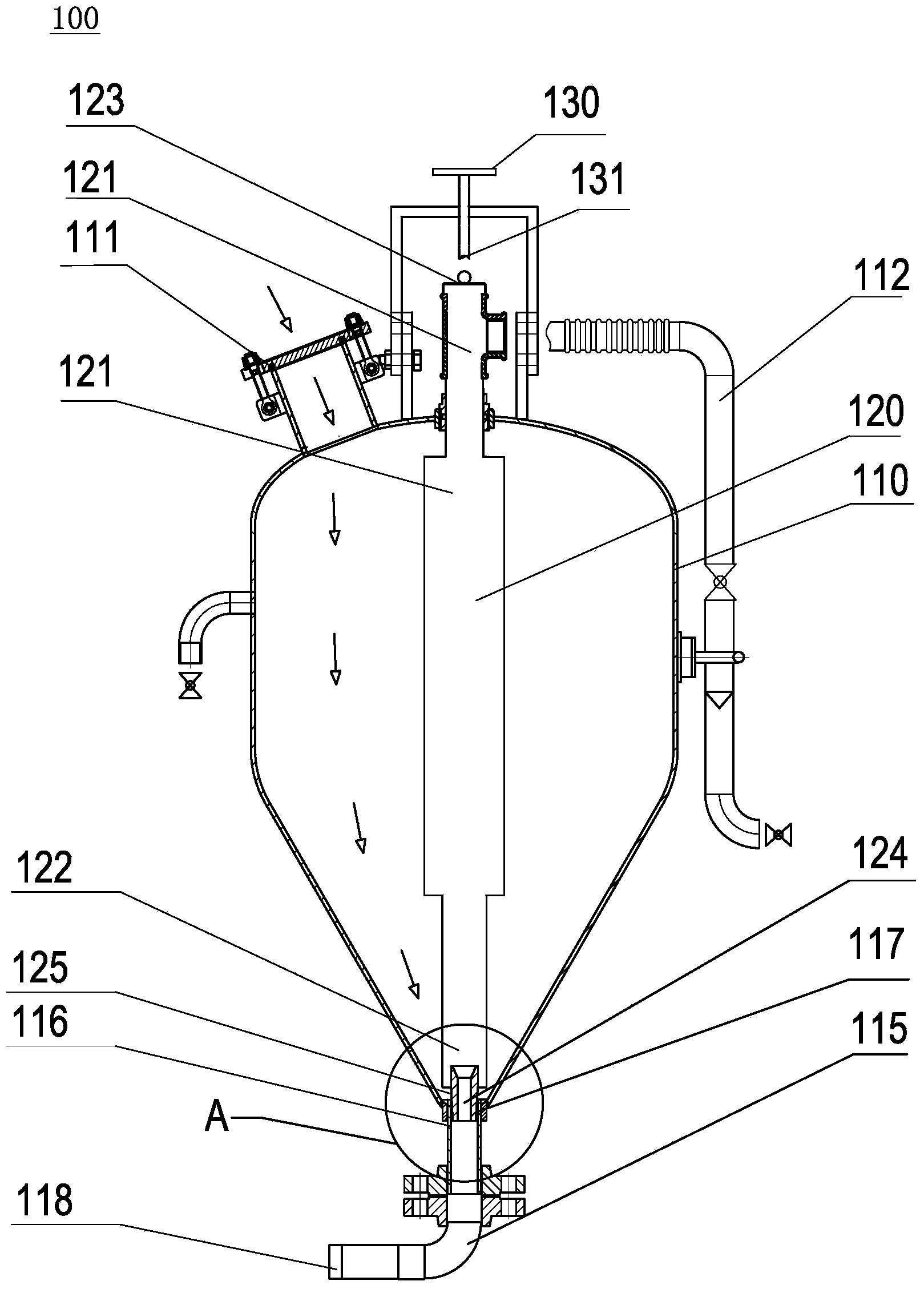
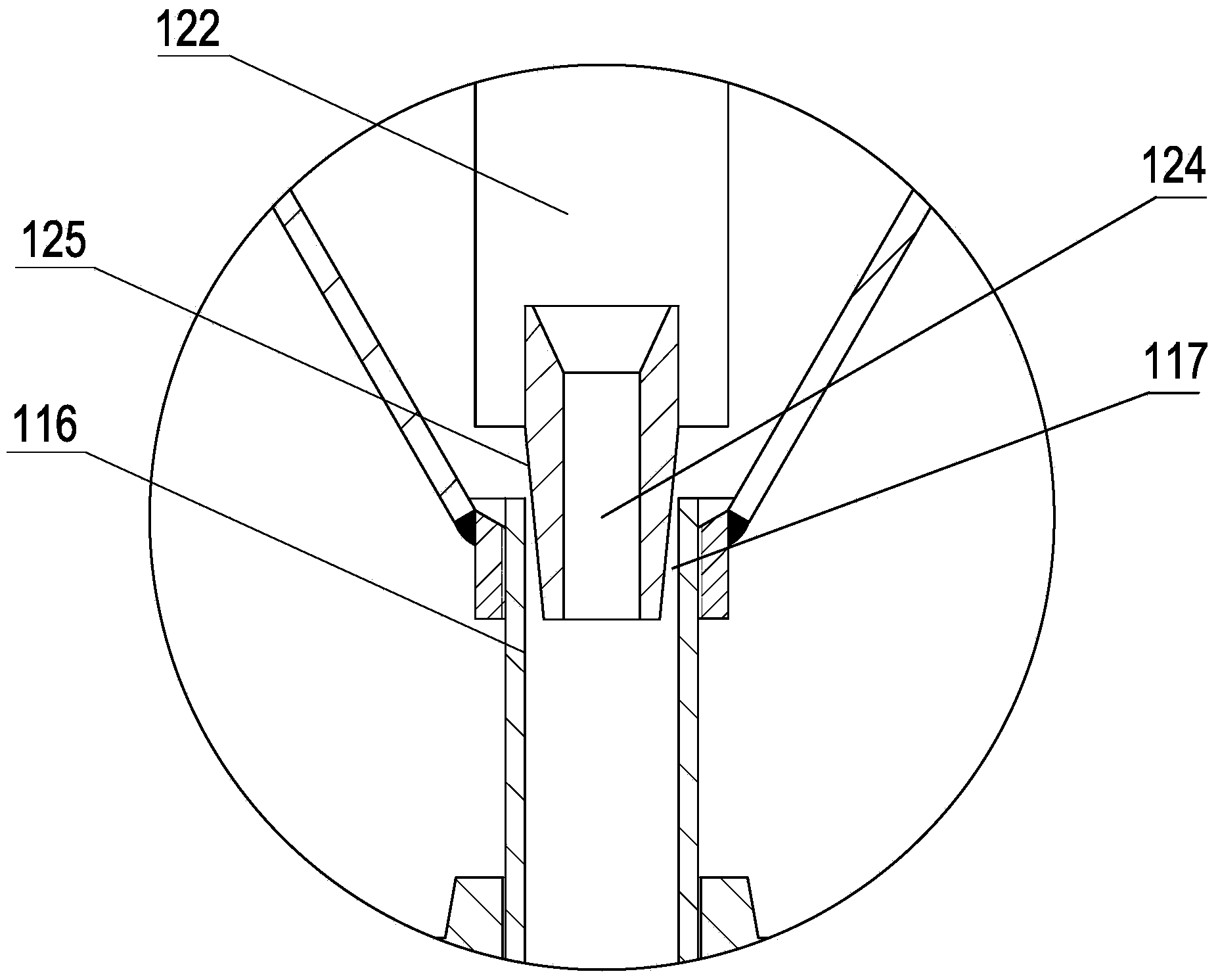
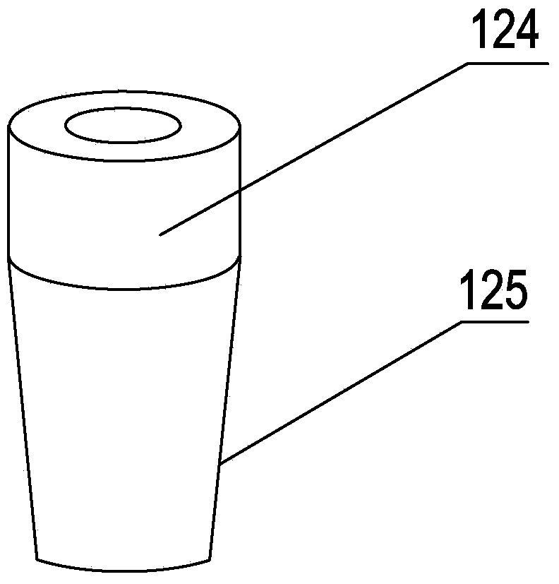
[0025] refer to figure 1 and figure 2 , a flow controllable continuous blasting machine 100, including a material tank 110, a center pipe 120, an adjusting rod 130 and an air compression device (not shown). The upper outer wall of the material tank 110 is provided with a feeding port 111 , and the lower outer wall is provided with an outlet pipe 115 connected to a sandblasting nozzle 118 . The central tube 120 has an upper part 121 , a lower part 122 and a top end 123 , and the lower part 122 is provided with a Venturi nozzle 124 . The upper part 121 of the central tube 120 is movably connected to the material tank 110 , the upper part passes through the top of the material tank 110 and can slide up and down relative to the top of the material tank 110 , and the rest is arranged inside the material tank 110 . The Venturi nozzle 124 protrudes into the outlet pipe 115 . The air compression device is provided with an air inlet pipe 112 , and the air inlet pipe 112 communicate...


PUM


Abstract

The invention provides a flow-controllable continuous sandblasting machine which comprises a charging bucket, a central pipe arranged in the charging bucket, an adjusting rod arranged at the top of the charging bucket and an air compression unit. The upper part of the charging bucket is provided with a feed inlet. The lower part of the charging bucket is provided with an outlet pipe which is connected with a sandblasting pipe and a sandblasting nozzle. The bottom of the central pipe is provided with a venturi nozzle which extends into the outlet pipe. The top of the central pipe is closed. The upper part of the central pipe passes through the top of the charging bucket and can slide up and down relative to the top of the charging bucket. The adjusting rod directly faces the upper part of the central pipe. The air compression unit is equipped with an air inlet pipe which is communicated with the upper part of the central pipe and is used for allowing dry compressed air to be entered into the central pipe from the air inlet pipe. According to the sandblasting machine, dry compressed air is used as a power source and baking soda is conveyed by the utilization of venturi principle. Thus, the problem that pipeline and nozzle obstruction caused by agglomeration of baking soda is solved.

Description

technical field [0001] The invention relates to the technical field of sandblasting machines, in particular to a continuous sandblasting machine with controllable flow rate, which is suitable for spraying substances prone to caking such as baking soda. Background technique [0002] Existing sandblasting machines are divided into suction type and push-in type. Using a sandblasting machine to spray baking soda can be used to clean and remove coatings, rust, and dirt on the surface of objects without damaging the substrate, but baking soda (carbonic acid) Sodium hydrogen) is easy to absorb water and agglomerate, has poor fluidity and is brittle, which leads to many defects in spraying baking soda with these two sandblasting machines. [0003] Suction type sandblasting machine uses the negative pressure generated by the high-speed movement of compressed air in the spray gun to suck the material into the sandblasting pipe, and the material is directly connected to the atmosphere....

Claims


Application Information

Patent Timeline
Patent Type & Authority Applications(China)
IPC IPC(8): B24C5/04B24C7/00
CPCB24C5/04B24C1/00B24C1/086B24C7/0038
Inventor 郭晓军
Owner 郭晓军
Why Eureka
Try Eureka