
Vacuum motor

A technology for vacuum motors and motor casings, which is applied in the direction of electrical components, electromechanical devices, electric components, etc., which can solve the problems of long-term stable operation of motors and rising costs, and achieve the effect of reducing temperature and improving service life

Inactive Publication Date: 2015-02-25
DONGGUAN NEUTRON SCI CENT
View PDF6 Cites 9 Cited by
  • Summary
  • Abstract
  • Description
  • Claims
  • Application Information

AI Technical Summary

Problems solved by technology

[0004] The present invention provides a vacuum motor to solve the problem that the current motor cannot run stably for a long time in a vacuum environment and the cost increases due to the vacuum sealing of the ordinary motor by using a sealed cavity

Method used


Image

  • Vacuum motor
  • Vacuum motor
  • Vacuum motor

Examples


Embodiment Construction

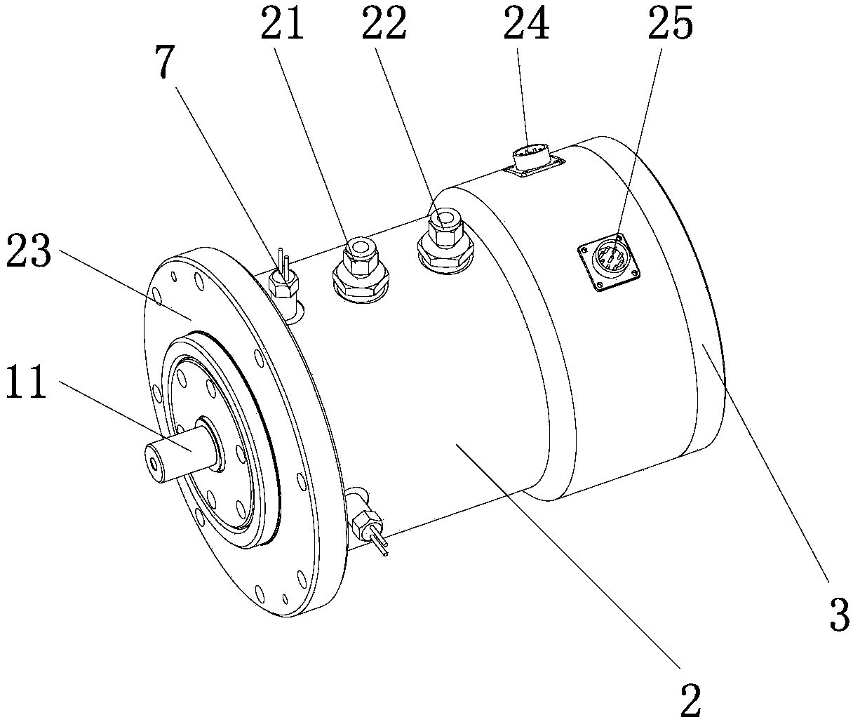
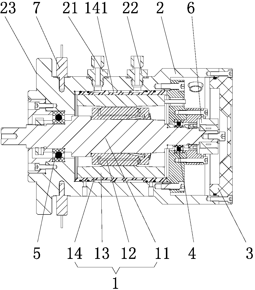
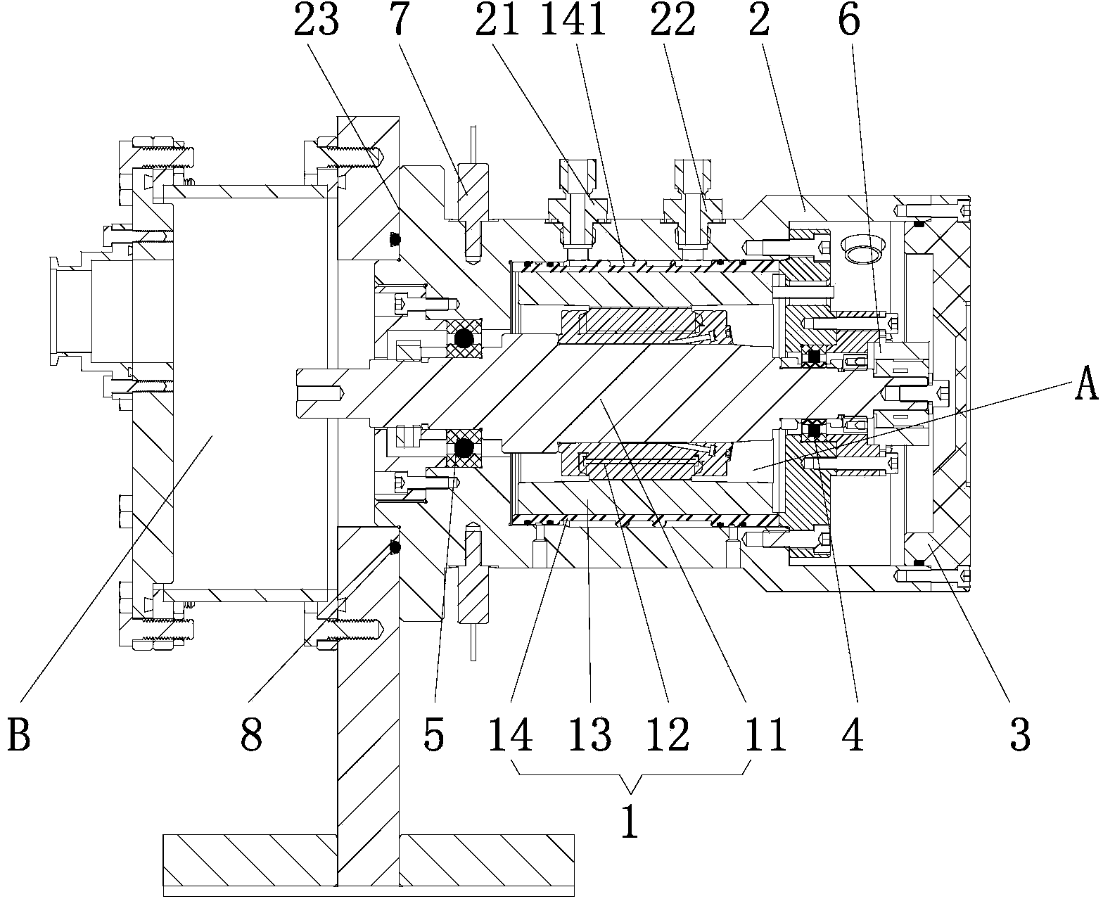
[0017] Attached below figure 1 to attach image 3 The present invention is described further:

[0018] Such as figure 1 with figure 2 The shown vacuum motor includes a motor main body 1, a motor housing 2 and a rear end cover 3, the motor main body 1 is arranged in the inner cavity of the motor housing 2, and the motor housing 2 is provided with a water inlet pipe joint 21 and a water outlet pipe joint 22 , the coolant enters the inner cavity of the motor housing 2 along the water inlet pipe joint 21 and flows out from the water outlet pipe joint 22 after cooling the motor body 1, the rear end cover 3 is sealed with the rear end of the motor housing 2, and the The front end face is a flat and smooth flange end face 23 . In this embodiment, cooling water is used as the cooling liquid.

[0019] In this embodiment, the motor body 1 adopts a built-in motor structure. The motor body 1 includes a main shaft 11, a rotor 12, a stator 13 and a cooling cover 14. The rotor 12 is fi...


PUM


Abstract

The invention relates to the field of electromechanical technology, in particular to a vacuum motor. The vacuum motor is provided with a water cooling and vibrating sensor interface and can be applied in the vacuum and radiation environment. The vacuum motor comprises a motor body, a motor shell and a rear end cover. The motor body is arranged inside an inner cavity of the motor shell. The motor shell is provided with a water inlet pipe connector and a water outlet pipe connector. Cooling liquid enters the inner cavity of the motor shell through the water inlet pipe connector, cools the motor body and flows out of the water outlet pipe connector. The rear end cover is in sealing connection with the rear end of the motor shell. The front end face of the motor shell is a flat and smooth flange end face. During installation, vacuum combination between the vacuum motor and other sealing cavities can be achieved only by sealing the flange end face through an O-shaped ring; in addition, the temperature of the vacuum motor can be effectively lowered through circulation of the cooling liquid, so that it is ensured that the vacuum motor can effectively run for a long time, and the service life of the vacuum motor is prolonged.

Description

technical field [0001] The invention relates to the field of electromechanical technology, in particular to a vacuum motor with water cooling and a vibration sensor interface, which can be applied in vacuum and radiation environments. Background technique [0002] Electric motors are one of the most commonly used devices in the electromechanical field, but motors designed for use in vacuum are uncommon. Under the condition of vacuum sealing, the heat dissipation of the motor is relatively difficult (the heat cannot be dissipated through air conduction), therefore, the motor cannot work stably for a long time, and the service life of the motor is also short. [0003] For applications that require a relatively high degree of vacuum, it is also necessary to consider the influence of the volatilization of the motor bearing grease on the degree of vacuum. At present, most of the vacuum motors on the market are grouped independently and are not sealed separately. When in use, a s...

Claims


Application Information

Patent Timeline
Patent Type & Authority Applications(China)
IPC IPC(8): H02K9/19H02K5/04
CPCH02K9/19H02K5/10H02K5/20
Inventor 蔡伟亮王平
Owner DONGGUAN NEUTRON SCI CENT
Learn More