
Continuous pass-type radiation scanning system and method

A technology of scanning system and scanning method, which is applied in the exploration of nuclear radiation, material analysis using radiation, measuring devices, etc., can solve the problems of high labor cost, false scanning of the front of the car, mistaken entry of the rear car into the detection channel, etc., and achieve high suspicion The ability to detect objects, prevent false scanning, and high detection efficiency

Active Publication Date: 2015-02-25
พาวเวอร์สแกน ไฮเทค โค แอลทีดี
View PDF5 Cites 38 Cited by
  • Summary
  • Abstract
  • Description
  • Claims
  • Application Information

AI Technical Summary

Problems solved by technology

However, this radiation scanning security inspection equipment must be used together with other auxiliary facilities. For example, indicating devices such as traffic lights and / or barrier bars must be set at the entrance of the detection channel to control the scanning process. During the current vehicle scanning process, the indicating device Block the following vehicles out of the detection channel, and guide the rear vehicle into the detection channel after the inspection of the preceding vehicle is completed
If this kind of indicating device is not installed, the rear car may enter the detection channel by mistake, causing the dose received by the rear car occupants to exceed the safety limit, and there is even a risk that the front of the rear car will be mistakenly scanned by the high dose rate rays that are being emitted. Some security inspection places even need to arrange special personnel to assist and guide, and the cost of equipment maintenance and labor is high

Method used


Image

  • Continuous pass-type radiation scanning system and method
  • Continuous pass-type radiation scanning system and method
  • Continuous pass-type radiation scanning system and method

Examples


Embodiment Construction

[0030] The technical solutions of the present invention will be described in detail below in conjunction with the accompanying drawings and specific embodiments.

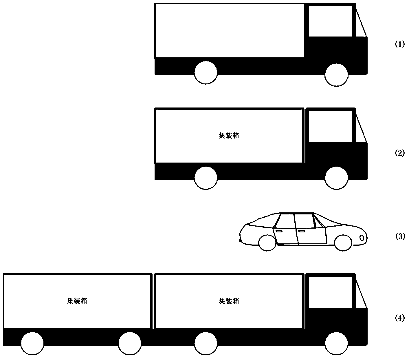
[0031] figure 1 Several different types of vehicles are exemplarily shown, for example (1) is an ordinary cargo vehicle, such as a container truck or a truck, and the gap between the front of the vehicle and the cargo compartment cannot be identified. (2) It is a container-type cargo vehicle, and the gap between the front and the container can be identified. (3) It is a container-type cargo vehicle towing two containers. (4) It is a small passenger vehicle, such as a car. to figure 1 Several car models shown are scanned as an example, and the principle, working process and technical details of the present invention are described. The applicable object of the present invention is not limited to figure 1 The models shown in , also apply to all similar models.

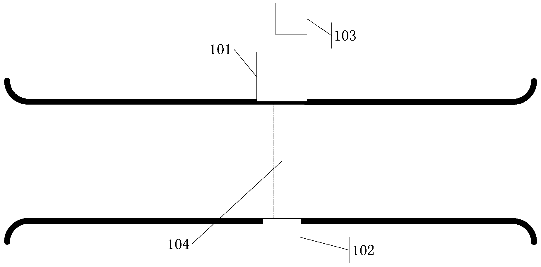
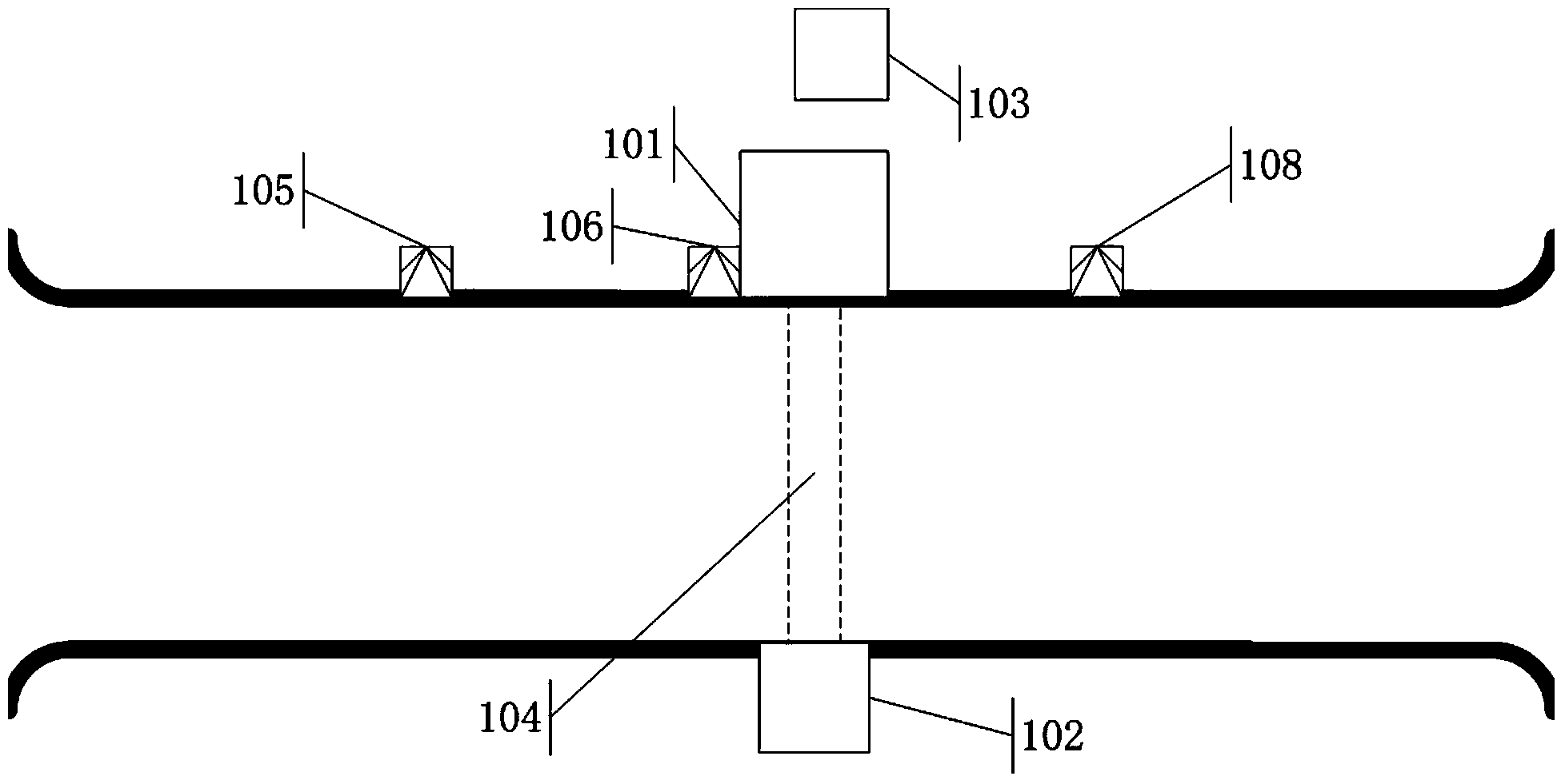
[0032] figure 2 A top view of a typical detection...


PUM

PropertyMeasurementUnit
Lengthaaaaaaaaaa

Abstract

The invention discloses a continuous pass-type radiation scanning system. The system comprises a radiation source, a collimator, a radiation detector, an imaging device, a first detection unit (105), a second detection unit (108) and a control module; the first detection (105) is used for detecting whether a target object achieves a preset position which is located at the upstream of a scanning region and apart from the upstream side border of the scanning region by a first length L1, wherein the scanning region is a region covered with radiation source rays in a detection channel; the second detection unit (108) is used for detecting whether a part required to be subjected to the scanning of low-dosage rate rays in the target object leaves a scanning region and a part required to be subjected to the canning of high-dosage rate rays in the target object is about to enter the scanning region; and the control module is used for receiving signals from various detection units and controlling the radiation source according to the signals. The system and the method disclosed by the invention can be used for achieving the condition that a large quantity of to-be-detected vehicles can continuously and fast pass through the detection channel to finish the radiation scanning examination.

Description

technical field [0001] The invention relates to the technical field of radiation imaging, in particular to the field of fast radiation imaging of moving targets, and in particular to a continuous-pass radiation scanning system and method. Background technique [0002] Scanning and inspecting vehicles and goods by using rays is a common method for border inspection and customs inspection at present. With the increasingly severe anti-terrorism situation and the need to combat smuggling, it is necessary to conduct radiation scanning inspections on all vehicles passing through the customs. In the case of a large number of customs clearance vehicles, in order to improve the inspection efficiency, it is necessary to implement rapid radiation imaging on the moving vehicles and complete the scanning in a short enough time, so that the vehicles to be inspected can be scanned and inspected without stopping. efficient. In this fast and continuous scanning inspection technology, one o...

Claims


Application Information

Patent Timeline
IPC IPC(8): G01N23/04G01V5/00
CPCG01V5/00
Inventor 王少锋闫雄
Owner พาวเวอร์สแกน ไฮเทค โค แอลทีดี
Learn More