
Powder sintering device

A sintering device and powder technology, applied in the direction of furnace, furnace type, lighting and heating equipment, etc., can solve the problems of poor dynamic sealing effect of rotary kiln, inability to effectively seal gas leakage, etc., and achieve good dynamic sealing effect

Active Publication Date: 2015-02-25
江苏合志新能源材料技术有限公司 +1
View PDF6 Cites 4 Cited by
  • Summary
  • Abstract
  • Description
  • Claims
  • Application Information

AI Technical Summary

Problems solved by technology

But its disadvantage is that the dynamic sealing effect of the rotary furnace is poor, and it cannot effectively seal the gas leakage.

Method used


Image

  • Powder sintering device
  • Powder sintering device
  • Powder sintering device

Examples


Embodiment Construction

[0014] The powder sintering device provided by the present invention will be further described in detail below in conjunction with the accompanying drawings and specific embodiments.

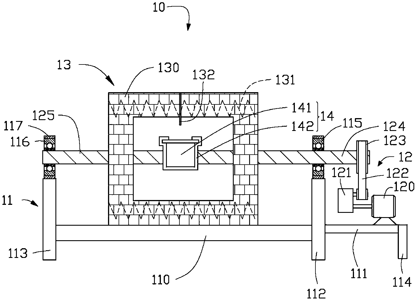
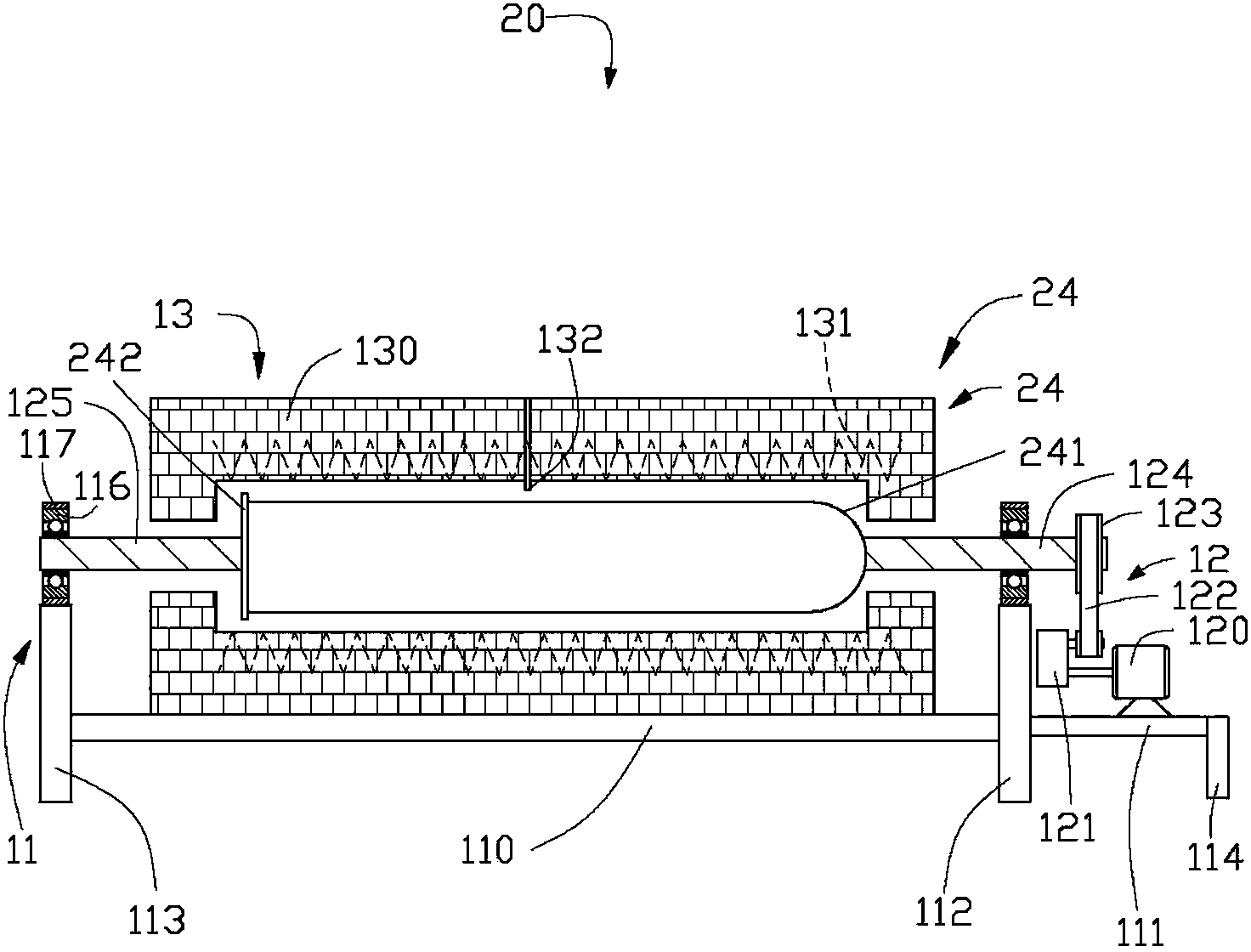
[0015] See figure 1 , The first embodiment of the present invention provides a powder sintering device 10 , the powder sintering device 10 includes a support unit 11 , a driving unit 12 , a sintering unit 13 , and a reaction unit 14 . The driving unit 12 is disposed on the support unit 11 , and the reaction unit 14 is disposed inside the sintering unit 13 .

[0016] The support unit 11 includes a first beam 110 , a second beam 111 , a first vertical beam 112 , a second vertical beam 113 , a third vertical beam 114 , a first bearing 115 and a second bearing 116 . The first beam 110 is supported by the first vertical beam 112 and the second vertical beam 113 , and the second beam 111 is supported by the first vertical beam 112 and the third vertical beam 114 . The first bearing 115 is arranged o...


PUM


Abstract

The invention relates to a powder sintering device. The powder sintering device comprises a supporting unit, a driving unit, a sintering unit and a reaction unit. The driving unit is arranged on the supporting unit; the reaction unit is arranged inside the sintering unit, can be heated through the sintering unit, is fixed in the driving unit, and can be driven by the driving unit to rotate. In addition, the invention further provides a method for preparing composite materials through the powder sintering device.

Description

technical field [0001] The invention relates to a powder sintering device, in particular to a rotatable powder sintering device. Background technique [0002] For the preparation process of inorganic materials, the sintering process is one of the important links. From the perspective of sintering state, it is mainly divided into static sintering and dynamic sintering. Dynamic sintering can realize the sintering of various materials while mixing, and it is easier to achieve accurate local stoichiometric ratio of materials and avoid the generation of impurity phases. From the perspective of dynamic sintering equipment, industrial furnaces are mainly rotary furnaces, which rotate while sintering during the sintering process. But its disadvantage is that the dynamic sealing effect of the rotary kiln is poor, and the gas leakage cannot be effectively sealed. For some toxic gases such as sulfur and phosphorus in the sintering process, it is necessary to develop new sintering eq...

Claims


Application Information

Patent Timeline
Patent Type & Authority Applications(China)
IPC IPC(8): F27B21/00
CPCB22F3/003B22F3/10F27B17/0016B22F3/1039
Inventor 何向明张建利王莉李建军罗晶尚玉明
Owner 江苏合志新能源材料技术有限公司
Learn More