
A land-air amphibious vehicle

A vehicle, land-air technology, applied in the field of land-air amphibious vehicles, can solve the problems of endangering life safety, single structure, no technical solution, etc., and achieve the effect of prolonging the service life and improving safety performance

Active Publication Date: 2017-11-03
上海闯造科技有限公司
View PDF3 Cites 3 Cited by
  • Summary
  • Abstract
  • Description
  • Claims
  • Application Information

AI Technical Summary

Problems solved by technology

But through its patent application specification, we can't find its specific technical solution. It can be seen from the accompanying drawings of the specification that the structure of the flying car is unreasonable, and its main weight is concentrated on the front wheel of the bicycle. Once the engine fails, there are no preventive measures , very dangerous
French patent FR1265234 discloses a vehicle that can both drive on the ground and fly, but its structure is relatively simple and cannot meet the needs of multi-purpose
Chinese patent CN103350624A discloses a vehicle that can drive on the ground and fly, but its ground driving structure and flight structure are relatively simple and rough superimposed forms, which are not fully, effectively and reasonably integrated, and the propeller is not protected. During the flight, the propeller rotates at a high speed. Once it encounters obstacles or people, it is easy to cause damage to itself or endanger people's life safety.
[0006] Based on the research of existing literature and existing related technologies, the inventors found that the flying cars reported or realized at home and abroad are basically fixed wings, which require a fixed runway, which greatly limits their application occasions
The existing methods for implementing the helical wing are basically in the theoretical stage, and the helical wing is huge, which is not conducive to practical application
There is no one feasible way to implement

Method used


Image

  • A land-air amphibious vehicle
  • A land-air amphibious vehicle
  • A land-air amphibious vehicle

Examples


Embodiment 1

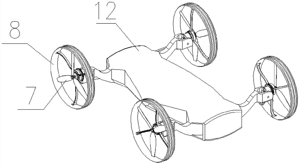
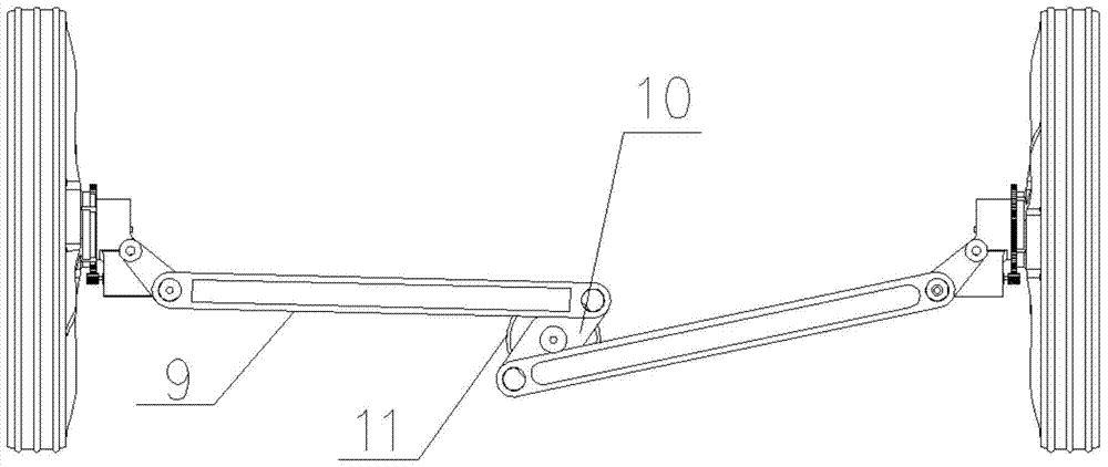
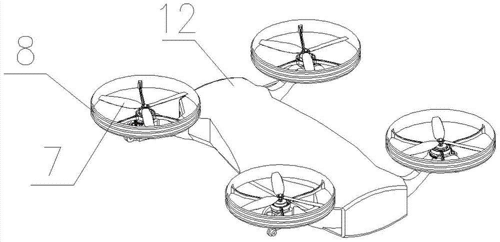
[0040] Such as Figure 1-6 As shown, a land-air amphibious vehicle includes a vehicle body base 12, a power mechanism, a transmission mechanism, and a drive assembly. The power of the power mechanism drives the drive assembly through the transmission mechanism, and the drive assembly is deformably arranged on the On the vehicle body base 12, it can fly in the air by overcoming air resistance and its own gravity or travel on the ground by overcoming ground friction.

[0041] The land-air amphibious vehicle also includes a control module and a communication module, the power mechanism includes a battery and a motor, the control module and the motor are electrically connected to the battery, and the communication module is used to establish the The communication link between the amphibious vehicle and the outside world. The communication module may include information collection equipment, information storage equipment, information sending device and information receiving device...

Embodiment 2

[0053] Such as Figure 7-8 As shown, compared with Embodiment 1, the difference of this embodiment is: a motor is installed on each of the wing assemblies, the motor is a high and low speed motor 13, and the flight propeller 7 and the hub 8 are the same. The shafts are fixedly connected, and each of the high and low speed motors 13 drives the flight propeller 7 and the hub 8 mounted on the wheel assembly of the high and low speed motors 13 to rotate simultaneously.

[0054] The flying propeller 7 and the hub 8 in this implementation are all synchronously rotating in the air flight state and the ground driving state. The rotating speeds of the high and low speed motors 13 are different under the above two states, and the high and low speed motors 13 are automatically controlled by manual or control modules to rotate at low speeds. Or high-speed rotation, select low-speed rotation when driving on the ground, and high-speed rotation when flying in the air.

Embodiment 3

[0056] Such as Figure 9 As shown, compared with Embodiment 1, the difference of this embodiment is that: a motor and a transmission mechanism are installed on each of the wheel wing assemblies, and the transmission mechanism includes a gearbox 14 and a clutch. The box 14 includes an input shaft and two output shafts, a driving gear 15 is installed on the input shaft, and a driven gear 16 is installed on the two output shafts, and the driven gears 16 are hub drive gears respectively 17 and flight propeller drive gear 18, the hub 8 is coaxially fixedly connected with a hub gear meshed with the hub drive gear 17, and the flight propeller 7 is coaxially fixedly connected with a hub gear meshed with the flight propeller drive gear 18 The flying propeller gear, the clutch is used to switch the engagement of the driving gear 15 on the input shaft with the hub driving gear 17 or the flying propeller driving gear 18.

[0057] The cockpit is provided with a clutch switch linked with t...


PUM


Abstract

The invention discloses a ground-air amphibious vehicle, which comprises a vehicle body base, a power mechanism, a transmission mechanism and a drive assembly. The power of the power mechanism is driven by the transmission mechanism to drive the drive assembly. On the body base, it can fly in the air by overcoming air resistance and its own gravity or travel on the ground by overcoming ground friction. The beneficial effects of the present invention are: the flight propeller and the running assembly are combined into a deformable wheel wing assembly, and the power drives the running assembly to move at a low speed when driving on the ground; when flying in the air, the wheel wing assembly is deformed by the steering gear , so that the plane of rotation of the flying propeller is located in the horizontal plane, at this time the power is transmitted to the flying propeller through the transmission mechanism to make the flying propeller rotate at a high speed to provide lift.

Description

technical field [0001] The invention relates to a vehicle, in particular to a land-air amphibious vehicle. Background technique [0002] With the vigorous development of computer technology, communication technology and electronic technology, the research on automotive aircraft has gradually formed an upsurge in the world, but it is still in the design concept stage, and many technical problems are still difficult to solve. Compared with helicopters, fixed-wing aircraft has the advantages of high flight efficiency, fast flight speed, long flight distance, simple system structure, light weight, low cost and use fee, etc., but fixed-wing aircraft also has its own inevitable defects, that is, in Takeoff and landing require taxiing or use of special launch recovery devices. [0003] Vertical take-off and landing technology makes it possible for aircraft to combine the performance and advantages of helicopters and fixed wings. At present, the more successful vertical take-off a...

Claims


Application Information

Patent Timeline
Patent Type & Authority Patents(China)
IPC IPC(8): B60F3/00
Inventor 蔡闯
Owner 上海闯造科技有限公司
Learn More