
Vertical machining device

A processing device and vertical technology, applied in the field of mechanical processing, can solve the problems of high labor intensity, tilting and offset of the processing chassis, and inability to lift accurately, so as to improve efficiency and quality, avoid tilting and offset, and achieve fast and efficient processing.

Inactive Publication Date: 2015-02-25
TONGXIANG SHENGHUI PRECISION MACHINERY
View PDF5 Cites 11 Cited by
  • Summary
  • Abstract
  • Description
  • Claims
  • Application Information

AI Technical Summary

Problems solved by technology

[0002] The mechanical workpiece is a single piece that makes up the machine and its inseparability. It plays an important role in the automation industry. The mechanical workpiece includes the connection of parts, the supporting parts, the lubricating lubrication system and the sealing Parts, parts of the transmission system that transmit motion and energy, in the process of processing mechanical workpieces, generally use the processing device to finish the mechanical workpiece. When the traditional processing device places the workpiece for processing, according to Due to the needs of workpiece processing, it is difficult to accurately translate the workpiece. Generally, the workpiece is translated manually, and the labor intensity of the workers is relatively high. When the existing processing device is processing the workpiece, the processing motor is used to drive the processing tool to perform high-speed The workpiece is processed by rotation, and the rotation speed of the processing tool cannot be adjusted according to the material of the workpiece, which reduces the scope of application of the processing device and the processing quality. The chassis is often tilted and offset, and cannot be lifted and lowered accurately, which reduces the service life and processing quality of the processing device, and cannot meet the normal production needs

Method used


Image

  • Vertical machining device
  • Vertical machining device
  • Vertical machining device

Examples


Embodiment Construction

[0015] In order to further describe the present invention, a specific implementation of a vertical processing device will be further described below in conjunction with the accompanying drawings. The following examples are explanations of the present invention and the present invention is not limited to the following examples.

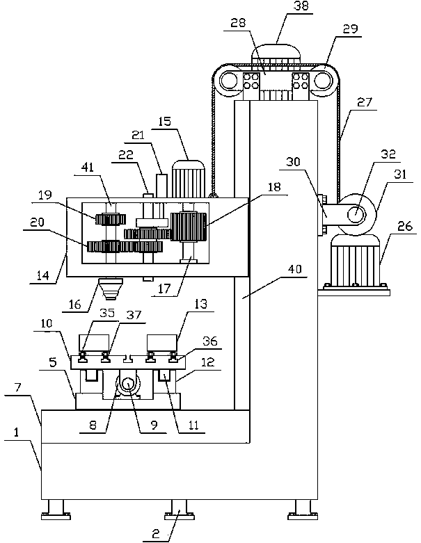
[0016] Such as figure 1 As shown, a vertical processing device of the present invention includes a main support 1, a workpiece fixing mechanism and a processing mechanism. The lower side of the main support 1 is vertically provided with a plurality of legs 2, and the workpiece fixing mechanism is horizontally arranged on the main support 1. The processing mechanism is arranged horizontally above the workpiece fixing mechanism. Such as Figure 4 As shown, the workpiece fixing mechanism of the present invention includes a lower translation mechanism, an upper translation mechanism and a fixing fixture 13, and the lower translation mechanism includes a l...


PUM


Abstract

The invention discloses a vertical machining device and belongs to the technical field of machining. The vertical machining device comprises a main support, a workpiece fixing mechanism and a machining mechanism. The workpiece fixing mechanism is horizontally arranged on the main support, the machining mechanism is horizontally arranged above the workpiece fixing mechanism, and the workpiece fixing mechanism comprises a lower horizontal-moving mechanism, an upper horizontal-moving mechanism and a fixing clamp. The machining mechanism comprises a machining case, a machining motor and a machining tool. The machining case is horizontally arranged on the upper side of the main support, a lifting mechanism is vertically arranged on one side of the machining case, the machining motor is vertically arranged downwards on the upper side of the machining case, an input shaft is vertically arranged in the machining case, and a connecting mechanism is vertically arranged in the machining case. One side of the connecting mechanism is provided with an output shaft, the machining tool is arranged below the output shaft, and the main support is provided with a lifting fixing mechanism. The vertical machining device is simple in structure, convenient to operate and capable of fast, efficiently and accurately machining a workpiece and meeting the requirements of production.

Description

technical field [0001] The invention relates to a processing device, in particular to a vertical processing device, which belongs to the technical field of mechanical processing. Background technique [0002] The mechanical workpiece is a single piece that makes up the machine and its inseparability. It plays an important role in the automation industry. The mechanical workpiece includes the connection of parts, the supporting parts, the lubricating lubrication system and the sealing Parts, parts of the transmission system that transmit motion and energy, in the process of processing mechanical workpieces, generally use the processing device to finish the mechanical workpiece. When the traditional processing device places the workpiece for processing, according to Due to the needs of workpiece processing, it is difficult to accurately translate the workpiece. Generally, the workpiece is translated manually, and the labor intensity of the workers is relatively high. When the ...

Claims


Application Information

Patent Timeline
Patent Type & Authority Applications(China)
IPC IPC(8): B23Q5/10B23Q5/14B23Q5/40B23Q3/06B23Q1/25B23D79/00
CPCB23Q5/10B23D79/00B23Q1/25B23Q3/06B23Q5/14B23Q5/402
Inventor 谢欣航
Owner TONGXIANG SHENGHUI PRECISION MACHINERY
Learn More