A Worktable Mechanism of Compound Machining Center

A composite processing and workbench technology, applied in metal processing machinery parts, metal processing equipment, manufacturing tools, etc., can solve problems such as increasing labor intensity, reducing work efficiency, and affecting processing accuracy, achieving reasonable structural design and ensuring lubrication effects. , The effect of smooth oil circuit

Active Publication Date: 2017-01-11
太仓畅通精密机械有限公司
View PDF9 Cites 0 Cited by
  • Summary
  • Abstract
  • Description
  • Claims
  • Application Information

AI Technical Summary

Problems solved by technology

[0004] These two machining centers are often independent structures. When a workpiece needs to be processed vertically and horizontally, it is necessary to manually move the workpiece from one machining center to another, which not only reduces work efficiency and increases Labor intensity, and the multiple clamping of the workpiece also has an impact on the machining accuracy

Method used


Image

  • A Worktable Mechanism of Compound Machining Center
  • A Worktable Mechanism of Compound Machining Center
  • A Worktable Mechanism of Compound Machining Center

Examples


Embodiment Construction

[0047] The present invention will be further described in detail below in conjunction with the accompanying drawings and examples. The following examples are explanations of the present invention and the present invention is not limited to the following examples.

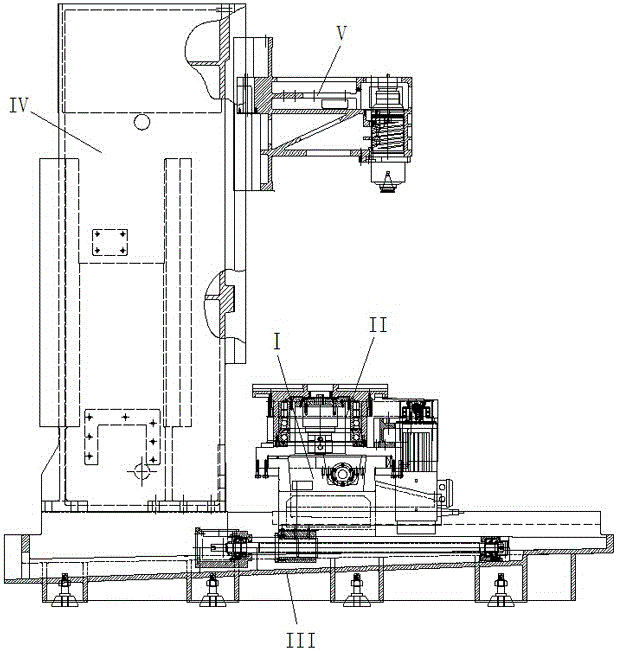
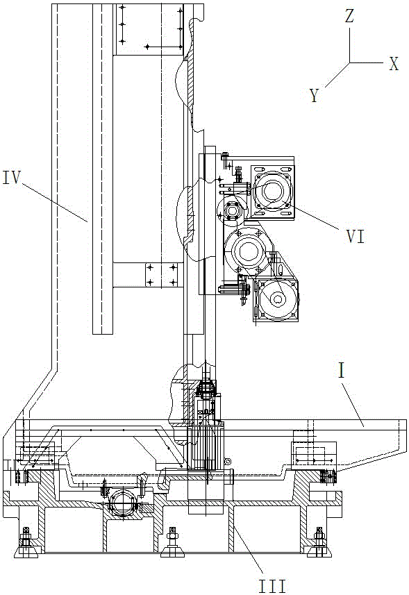
[0048] see Figure 1 to Figure 23 , the three coordinate axes of the X-axis, Y-axis, and Z-axis of the spatial coordinate system where the composite machining center is applied are set as follows: from the front of the composite machining center, the X-axis is placed horizontally, pointing to The left and right direction; the Y axis is placed horizontally, pointing to the front and rear directions; the Z axis is placed vertically, pointing to the up and down direction. In this application document, the X-axis, Y-axis, and Z-axis all refer to the coordinate axes set above.

[0049] The composite machining center to which the present invention is applied includes bed components and column components.

[0050] The be...


PUM


Abstract

The invention provides a workbench mechanism of a compound machine center. The workbench mechanism is reasonable in structural design. A workbench drive mechanism, a bearing assembly and a workbench positioning and locking mechanism are improved, so that the structure is more reasonable and efficient, and the function is better. A sliding saddle assembly comprises a sliding saddle. A workbench assembly comprises a workbench, a workbench seat, the workbench driving mechanism, the bearing assembly, a workbench brake mechanism and the workbench positioning and locking mechanism. The bearing assembly comprises first bearings. The workbench drive mechanism further comprises a small synchronous belt pulley, a big synchronous belt pulley, a synchronous belt, a pressing cap, a drive sleeve, a workbench motor seat and second bearings. The workbench brake mechanism comprises a brake hydraulic cylinder, a brake rotating plate, a brake drive body, brake embracing clamps, brake screw rods and brake nuts. When the number of the first bearings is at least two, and the first bearings are sequentially arrayed from top to bottom, the bearing assembly further comprises a bearing oil returning space ring. The workbench positioning and locking mechanism comprises a locking cylinder, a gear locking rod and a positioning gear ring.

Description

technical field [0001] The invention relates to a workbench mechanism of a compound machining center, which belongs to the field of general machine tools. Background technique [0002] Machining centers are widely used in the manufacturing industry. The current machining centers are mainly divided into vertical machining centers and horizontal machining centers. [0003] A vertical machining center is the Chinese patent of the vertical machining center with the application number 201110361110.7 and the title. A horizontal machining center is a Chinese patent with application number 201320056230.0 and a name of a horizontal machining center. [0004] These two machining centers are often independent structures. When a workpiece needs to be processed vertically and horizontally, it is necessary to manually move the workpiece from one machining center to another, which not only reduces work efficiency and increases Labor intensity, and the multiple clamping of the workpiece ...

Claims


Application Information

Patent Timeline
Patent Type & Authority Patents(China)
IPC IPC(8): B23Q1/26
CPCB23Q1/26
Inventor 黄品剑
Owner 太仓畅通精密机械有限公司
Why Eureka
Try Eureka