Lens vignetting compensation method and system

A lens vignetting and compensation method technology, applied in the field of lens vignetting compensation methods and systems, can solve the problems of limited size, increased chip manufacturing cost, limited storage of correction coefficient tables, etc., and achieve high-quality vignetting compensation and reduction. The effect of manufacturing size and reducing manufacturing cost

Inactive Publication Date: 2015-02-18
GUANGDONG VIMICRO ELECTRONICS CO LTD
View PDF8 Cites 6 Cited by
  • Summary
  • Abstract
  • Description
  • Claims
  • Application Information

AI Technical Summary

Problems solved by technology

[0009] In view of this, the embodiment of the present invention provides a new lens vignetting compensation method and system, which solves the problem of limited storage of the correction coefficient table and chip manufacturing cost in the prior art due to the limited size of the on-chip SRAM. additional questions

Method used


Image

  • Lens vignetting compensation method and system
  • Lens vignetting compensation method and system
  • Lens vignetting compensation method and system

Examples


Embodiment Construction

[0029] The following will clearly and completely describe the technical solutions in the embodiments of the present invention with reference to the accompanying drawings in the embodiments of the present invention. Obviously, the described embodiments are only some, not all, embodiments of the present invention. Based on the embodiments of the present invention, all other embodiments obtained by persons of ordinary skill in the art without making creative efforts belong to the protection scope of the present invention.

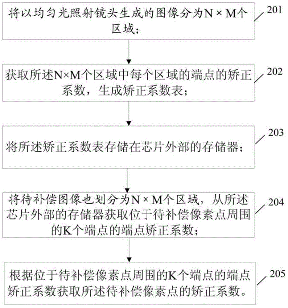
[0030] figure 2 Shown is a schematic flowchart of a lens vignetting compensation method provided by an embodiment of the present invention. Such as figure 2 As shown, the lens vignetting compensation method includes:

[0031] Step 201: Divide the image generated by irradiating the lens with uniform light into N×M regions.

[0032] Each of these regions is a rectangle with four endpoints. The purpose of irradiating the lens with uniform light is to make t...


PUM


Abstract

An embodiment of the invention provides a lens vignetting compensation method and system and solves the problems of the prior art that due to small size of a static random access memory of a chip, storage limitation of a compensation coefficient list occurs, and chip production cost increases. The lens vignetting compensation method includes dividing an image generated by a uniform light lighting lens into N*M areas; acquiring endpoint compensation coefficients of endpoints of the areas to generate the compensation coefficient list; saving the compensation coefficient list in a memory outside the chip; dividing an image to be compensated into N*M areas, and acquiring the endpoint compensation coefficients of K endpoints around pixel points to be compensated from the memory outside the chip; based on the endpoint compensation coefficients of K endpoints around the pixel points to be compensated, acquiring compensation coefficients of pixel points to be compensated.

Description

technical field [0001] The invention relates to the field of image processing, in particular to a lens vignetting compensation method and system. technical background [0002] Lens vignetting is caused by the characteristics of the lens itself. Specifically, the light intensity at the edge of the lens is smaller than that in the central area of ​​the lens, resulting in darker vignetting around the image than in the central area. In order to eliminate vignetting, it is necessary to correct each pixel of the image with a correction coefficient. [0003] figure 1 Shown is a schematic diagram of the principle of the lens vignetting compensation method in the prior art. Such as figure 1 As shown, Ex represents the light intensity of the pixel point x to be compensated, and Eo represents the light intensity at the center o of the focal plane. The light intensity relationship between Ex and Eo is: θ is the light angle between the light source and the pixel point x to be compe...

Claims


Application Information

Patent Timeline
Patent Type & Authority Applications(China)
IPC IPC(8): H04N5/357
Inventor 吴大斌李国新
Owner GUANGDONG VIMICRO ELECTRONICS CO LTD
Why Eureka
Try Eureka