
Battery pack power supply circuit capable of achieving over-temperature protection

A technology for over-temperature protection and battery packs, applied in battery circuit devices, emergency protection circuit devices, circuit devices, etc., can solve problems such as traffic accidents, dangers, battery pack temperature out of control, etc., to prolong service life, avoid damage, and ensure The effect of stable and safe power supply

Active Publication Date: 2015-02-18
SHENZHEN ZHUONENG NEW ENERGY TECH
View PDF5 Cites 8 Cited by
  • Summary
  • Abstract
  • Description
  • Claims
  • Application Information

AI Technical Summary

Problems solved by technology

The battery pack is generally composed of several battery cells in series, and the temperature switch detects the ambient temperature near it. If the battery core with severe heat is far away from the temperature switch, then when the temperature switch detects overheating, the battery with severe heat will The core may be damaged, especially when the temperature rises rapidly and the temperature switch has not responded, the temperature of the entire battery pack may have been out of control
In addition, the above-mentioned battery pack will directly cut off the power supply circuit after detecting overheating without sending an early warning signal, which is quite dangerous for high-speed vehicles and may easily cause serious traffic accidents

Method used


Image

  • Battery pack power supply circuit capable of achieving over-temperature protection
  • Battery pack power supply circuit capable of achieving over-temperature protection
  • Battery pack power supply circuit capable of achieving over-temperature protection

Examples


Embodiment Construction

[0022] Below in conjunction with accompanying drawing and specific embodiment, the present invention will be further described:

[0023] See figure 1 , the present invention relates to an uninterruptible power supply device for battery pack over-temperature protection, and its preferred embodiment includes a control circuit, several battery packs, several over-temperature detection circuits, and several charge-discharge drive circuits; battery packs, over-temperature detection circuits and charging There is a one-to-one correspondence between the discharge drive circuits.

[0024] Several battery packs are connected in parallel. Each battery pack includes several battery cells B0 connected in series. The positive terminal of each battery pack is connected to the positive output terminal PACK+ of the device, and the negative terminal of each battery pack is connected to the negative output terminal PACK- of the device through a corresponding charge and discharge drive circuit...


PUM


Abstract

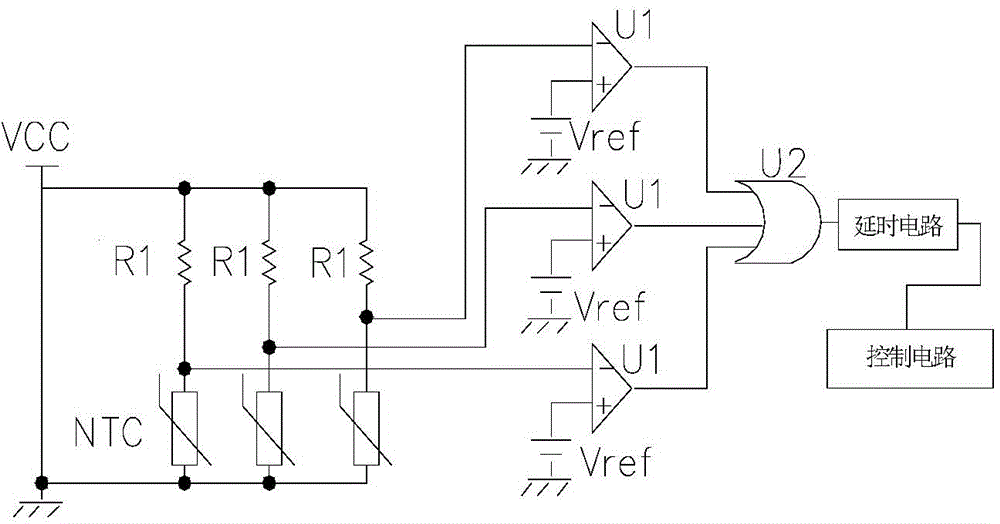
An uninterruptable battery pack power supply device capable of achieving over-temperature protection comprises a control circuit, a plurality of battery packs in parallel connection, a plurality of over-temperature detection circuits and a plurality of charge-discharge driving circuits. Each battery pack comprises cells in series connection, the anode end of each battery pack is connected with the positive output end of the device, and the cathode end of each battery pack is connected with the negative output end of the device through the corresponding charge-discharge driving circuit. Each over-temperature detection circuit is used for detecting temperatures of the cells of the corresponding battery pack and comparing temperature values of the cells with a preset safety temperature threshold value; when the temperature values of the cells are smaller than the preset temperature threshold value, the over-temperature detection circuit outputs normal temperature signals to the control circuit so as to drive the corresponding charge-discharge driving circuit to be conducted; when the temperature value of at least one of the cells is larger than the preset safety temperature threshold value, the over-temperature detection circuit outputs over-temperature signals to the control circuit so as to control the corresponding charge-discharge driving circuit to be cut off. The uninterruptable battery pack power supply device capable of achieving over-temperature protection is capable of providing stable and safe power supply.

Description

technical field [0001] The invention relates to a battery pack over-temperature protection power supply circuit. Background technique [0002] With the development of society, the market demand for new energy battery packs is increasing, especially for high-end vehicles such as electric vehicles and scooters. When the temperature of the battery pack is too high, if it continues to be used (that is, charging or discharging), it will cause great damage to the battery pack, and even cause safety accidents such as fire and explosion. [0003] Such as figure 1 As shown, the existing over-temperature protection circuit of the battery pack uses a mechanical temperature switch or a resistive temperature switch installed near the battery pack to detect the ambient temperature of the battery pack, and the system performs power-off processing when over-temperature is detected. The battery pack is generally composed of several battery cells in series, and the temperature switch detect...

Claims


Application Information

Patent Timeline
Patent Type & Authority Applications(China)
IPC IPC(8): H02H7/18H02J7/00
Inventor 黄延新邓纶浩杨圣峯黄晓东何鹏彭建普凌敏科
Owner SHENZHEN ZHUONENG NEW ENERGY TECH
Learn More