
Secondary side passive waste heat removal system

A waste heat and active technology, applied in nuclear power generation, climate sustainability, emergency protection devices, etc., can solve the problem of increasing the construction and operation and maintenance costs of nuclear power plants, equipment installation, operation and maintenance costs, and operator errors. Risks and other issues to avoid power and operator errors, reduce construction costs and operation and maintenance costs, and reduce equipment purchases

Inactive Publication Date: 2015-02-18
CHINA NUCLEAR POWER TECH RES INST CO LTD +2
View PDF7 Cites 9 Cited by
  • Summary
  • Abstract
  • Description
  • Claims
  • Application Information

AI Technical Summary

Problems solved by technology

In the active pressurized water reactor nuclear power plant, in order to ensure that the decay heat of the core can be continuously discharged in the event of design basis accidents and beyond design basis accidents, a waste heat removal system is usually designed on the primary side. This method will cool the water tank It is installed in the containment vessel, occupying the available space of the containment vessel, and it is necessary to add a heat exchanger placed in the refueling water tank, which will increase the design and construction costs of the system. Once the heat transfer tube is damaged, it will also make the Primary circuit coolant leakage
In addition, this waste heat removal system requires the power supply inside and outside the plant, emergency equipment (such as expensive emergency diesel engines) and operator intervention under accident conditions, which increases the risk of operator error. On the other hand, the quantity of equipment is greatly increased, thereby increasing the cost of equipment purchase, installation, operation and maintenance, etc., and correspondingly increasing the construction cost and operation and maintenance cost of nuclear power plants

Method used


Image

  • Secondary side passive waste heat removal system
  • Secondary side passive waste heat removal system
  • Secondary side passive waste heat removal system

Examples


Embodiment Construction

[0021] Embodiments of the present invention will now be described with reference to the drawings, in which like reference numerals represent like elements.

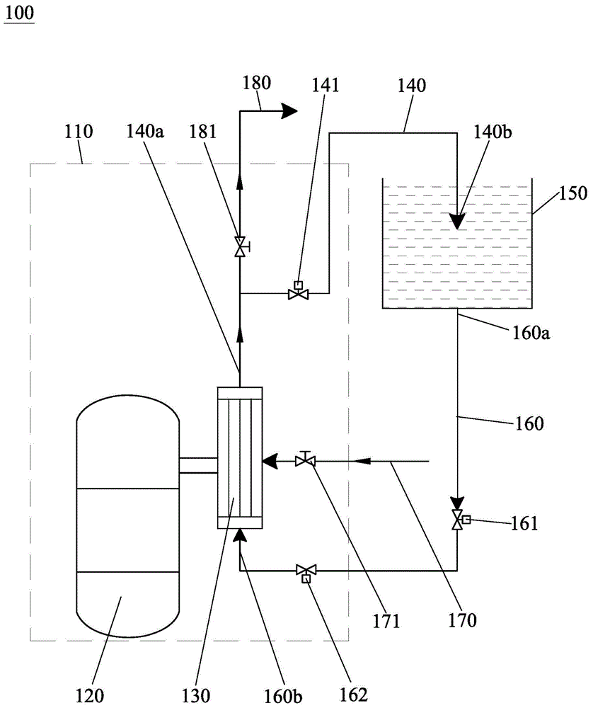
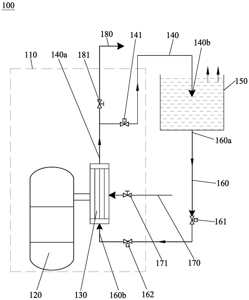
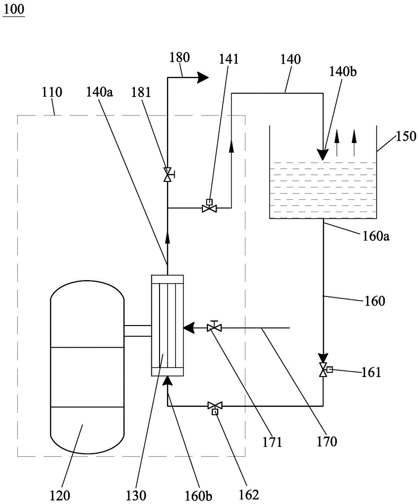
[0022] Such as figure 1 As shown, the secondary side passive waste heat removal system 100 provided by the present invention completely passively realizes the removal of core decay heat in the containment vessel 110 under an accident, and can reduce construction and operation and maintenance costs. The containment vessel 110 is provided with a reactor pressure vessel 120 and a steam generator 130 connected thereto. Generally speaking, a pressurized water reactor nuclear power plant is designed with two to four steam generators 130, and only one of them is shown in this embodiment. platform, and the setting of the remaining steam generators 130 is a technology well known to those skilled in the art. And the steam generator 130 is the only heat exchange equipment in this system, which is used for heat export of the primary...


PUM


Abstract

The invention discloses a secondary side passive waste heat removal system which comprises a steam pipeline and a water feeding pipeline, wherein the steam pipeline hermetically penetrates through a containment and is connected with the outlet of a steam generator in the containment as well as a cooling water tank which is arranged outside the containment; the water feeding pipeline hermetically penetrates through the containment and is connected with the cooling water tank and the inlet of the steam generator; the steam pipeline, the feeding water pipeline and the cooling water tank form a circulating channel so as to remove decay heat in the containment out of the containment. The steam pipeline and the feeding water pipeline are directly connected with the steam generator on the secondary side so as to prevent the steam generator from being burned and a coolant from being leaking. The cooling water tank is arranged outside the containment, so that available space of the containment is saved. Moreover, by using an open circuit, a heat exchanger which is required by the conventional passive waste heat removal system in the cooling water tank is not arranged, and no emergency equipment is required, so that the expenditure of design and construction of the system is lowered.

Description

technical field [0001] The invention relates to the field of nuclear power plant safety equipment, in particular to a secondary side passive residual heat derivation system for a pressurized water reactor nuclear power plant with a once-through steam generator. Background technique [0002] The use of nuclear power is a major breakthrough in the history of human energy utilization. The use of nuclear fission reactions can produce high energy output unmatched by all other traditional fossil energy sources, and these high energy outputs often only need to consume a small amount of nuclear fuel. The characteristics of low input and high output make mankind pay more and more attention to the utilization of nuclear energy, and continuously increase the research and development in the field of nuclear energy. Today, nuclear energy has become an important energy component in many countries in the world. However, while nuclear power has extremely high utilization value, it may also ...

Claims


Application Information

Patent Timeline
IPC IPC(8): G21C15/18
CPCG21C15/182G21C9/00G21C15/18Y02E30/30
Inventor 沈永刚卢向晖周洲芮旻张吉胜侯华青崔旭阳林支康
Owner CHINA NUCLEAR POWER TECH RES INST CO LTD
Learn More