
Light guide plate, backlight module and display

A light guide plate and light source technology, which is applied in the direction of instruments, light guides, optics, etc., can solve the problems of aggravating light output from the light guide plate, unevenness, uneven light output from the light guide plate, etc., and achieve the effect of improving the uniformity of light output

Active Publication Date: 2015-02-18
TCL CHINA STAR OPTOELECTRONICS TECH CO LTD
View PDF8 Cites 4 Cited by
  • Summary
  • Abstract
  • Description
  • Claims
  • Application Information

AI Technical Summary

Problems solved by technology

[0003] In the prior art, on the one hand, due to the loss of light in the transmission process, the brightness of the light emitted from the place farther away from the light source on the light-emitting surface of the light guide plate is relatively dark, which makes the light emitted from the light guide plate uneven; on the other hand, due to the specific The light output angle of the light guide plate will form a dark area corresponding to the gap between the two point light sources on the light output surface of the light guide plate, which will further aggravate the uneven light output of the light guide plate

Method used


Image

  • Light guide plate, backlight module and display
  • Light guide plate, backlight module and display
  • Light guide plate, backlight module and display

Examples


Embodiment Construction

[0024] The following will clearly and completely describe the technical solutions in the embodiments of the present invention with reference to the accompanying drawings in the embodiments of the present invention. Obviously, the described embodiments are some of the embodiments of the present invention, but not all of them. Based on the embodiments of the present invention, all other embodiments obtained by persons of ordinary skill in the art without creative efforts fall within the protection scope of the present invention.

[0025] Embodiments of the present invention provide a light guide plate, a backlight module, and a display, which can improve the uniformity of light output from the light guide plate and reduce light loss. The embodiments of the present invention will be described in detail below with reference to the accompanying drawings.

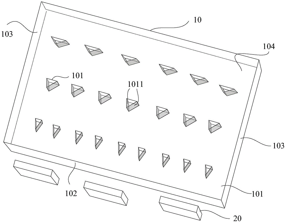
[0026] see figure 1 , is a schematic structural diagram of an embodiment of the light guide plate provided by the embodiment of...


PUM


Abstract

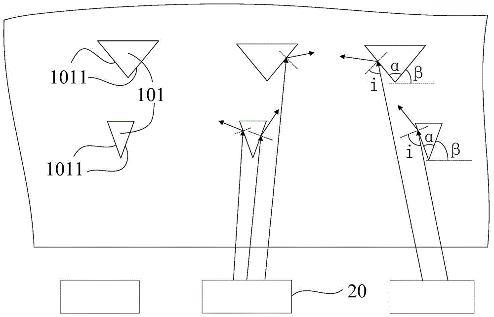
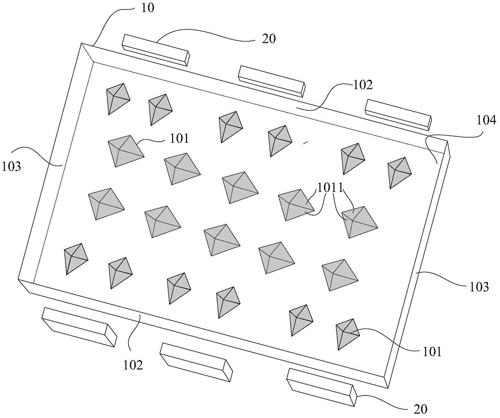
The embodiment of the invention relates to the display technical field, and discloses a light guide plate, a backlight module and a display. The light guide plate comprises a light-out face, a reflecting face opposite to the light-out face and at least one light-in face which is connected with the light-out face and the reflecting face. The reflecting face is provided with a plurality of micro protruding structures which protrude towards the inside of the light guide plate, each micro protruding structure comprises at least two side faces which are coated with high reflectivity materials, and the at least two corresponding side faces which are coated with the high reflectivity materials form at least one included angle facing the at least one light-in face. The shorter the distance of each micro protruding structure and a nearest light source, the smaller the at least one formed included angle. By means of the light guide plate, the backlight module and the display, incident light can be reflected to the positions corresponding to the gaps of the light sources, dark areas are prevented from being formed by the light guide plate at the gaps corresponding to the light sources, meanwhile, the light close to the light sources can be more reflected to the positions far away from the light sources, and thus light-out uniformity can be further improved.

Description

technical field [0001] The invention relates to the field of display technology, in particular to a light guide plate, a backlight module and a display. Background technique [0002] In the field of display technology, liquid crystal displays (Liquid Crystal Displays, LCDs) are currently widely used in the market. The liquid crystal molecules in the liquid crystal display do not have light-emitting properties, and need to rely on the backlight module to emit light to achieve the display effect. Generally speaking, the backlight module includes a light guide plate and multiple point light sources. The light emitted by the multiple point light sources can be emitted from the light-emitting surface of the light guide plate more uniformly through the reflection or scattering of the microstructures on the light guide plate. [0003] In the prior art, on the one hand, due to the loss of light in the transmission process, the brightness of the light emitted from the place farther ...

Claims


Application Information

Patent Timeline
Patent Type & Authority Applications(China)
IPC IPC(8): G02B6/00F21V8/00G02F1/13357
CPCG02B6/0055G02B6/0058G02B6/0036G02B6/00G02B6/0061G02B6/0068G02B6/0043
Inventor 周革革
Owner TCL CHINA STAR OPTOELECTRONICS TECH CO LTD
Learn More